Pin functions, 1 port pins – NEC uPD75P3116 User Manual
Page 7
µ
PD75P3116
7
Data Sheet U11369EJ3V0DS
3. PIN FUNCTIONS
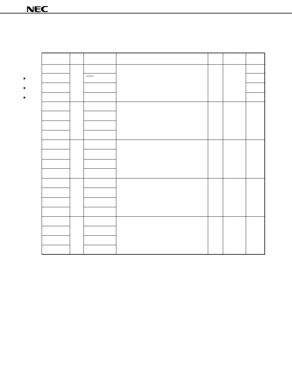
3.1 Port Pins (1/2)
Pin Name
I/O
Alternate
Function
8-Bit
Status
I/O Circuit
Function
I/O
After Reset
Type
Note 1
P00
Input
INT4
4-bit input port (Port 0)
—
Input
Connection of an internal pull-up resistor can be
P01
SCK
specified by a software setting in 3-bit units.
P02
SO/SB0
P03
SI/SB1
P10
Input
INT0
4-bit input port (Port 1)
—
Input
-C
Connection of an internal pull-up resistor can be
P11
INT1
specified by a software setting in 4-bit units.
P10/INT0 can be used to select a noise eliminator.
P12
TI1/TI2/INT2
P13
TI0
P20
I/O
PTO0
4-bit I/O port (Port 2)
—
Input
E-B
Connection of an internal pull-up resistor can be
P21
PTO1
specified by a software setting in 4-bit units.
P22
PCL/PTO2
P23
BUZ
P30
I/O
LCDCL/MD0
Programmable 4-bit I/O port (Port 3)
—
Input
E-B
Input and output can be specified in 1-bit units.
P31
SYNC/MD1
Connection of an internal pull-up resistor can be
specified by a software setting in 4-bit units.
P32
MD2
P33
MD3
P50
Note 2
I/O
D4
N-ch open-drain 4-bit I/O port (Port 5)
—
High
M-E
When set to open-drain, the withstanding voltage
impedance
P51
Note 2
D5
is 13 V.
P52
Note 2
D6
P53
Note 2
D7
Notes 1. Circuit types enclosed in angle brackets indicate Schmitt-triggered input.
2. The low-level input leakage current increases when input instructions or bit manipulation instructions are
executed.