0 operation, 1 power-up, 2 led status monitors – Patton electronic 1053 User Manual
Page 14: Operation, Power-up, Led status monitors
14
5.0 OPERATION
Once the Model 1053 is properly configured and installed, it should oper-
ate transparently. This sections describes power-up, reading the LED
status monitors.
5.1 POWER-UP
Before applying power to the Model 1053, read section 4.3, “Power Con-
nection” on page 12 to ensure that the unit is connected to the appropri-
ate power source.
5.2 LED STATUS MONITORS
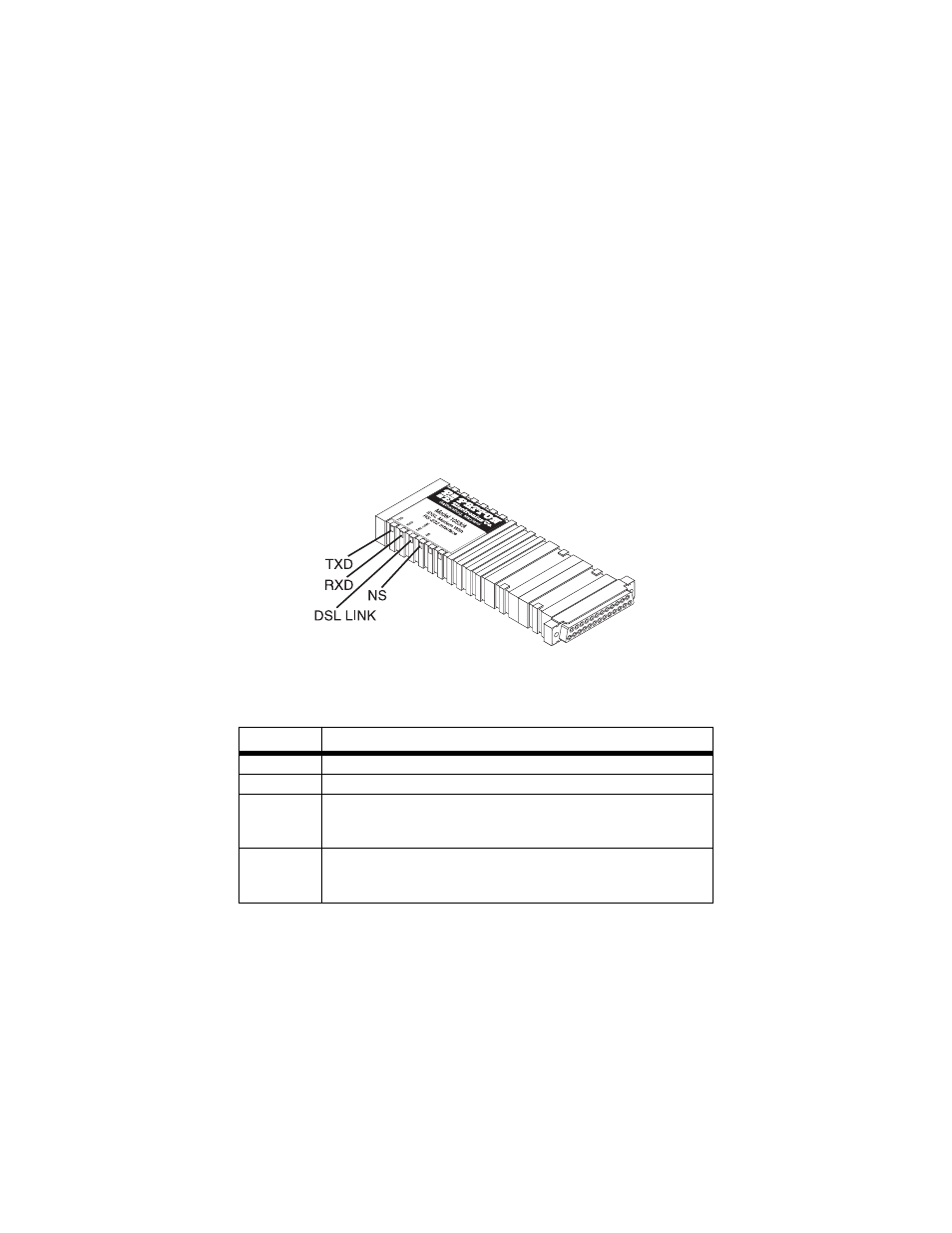
The Model 1053 features six side-panel LEDs (see Figure 7). Table 1
describes the function of each LED.
Figure 7.
Model 1053 side panel LEDs
Table 1:
LED descriptions
LED
Description
TXD
(Active: Green) When lit, indicates data transmission.
RXD
(Active: Green) When lit, indicates data transmission.
LINK
(Active: Green) When lit, indicates that the end-to-end DSL
framer link is up, signifying that the link across the DSL span
is active. The DSL Link LED is off when the link is down.
NS
(Active: Yellow) When the No Signal LED is lit, it indicates
that the local Model 1053 is not connected with the remote
Model 1053