Premier Mounts GB-PIPE1B User Manual
Page 6
Page 6
Installation Instructions
GB-PIPE1
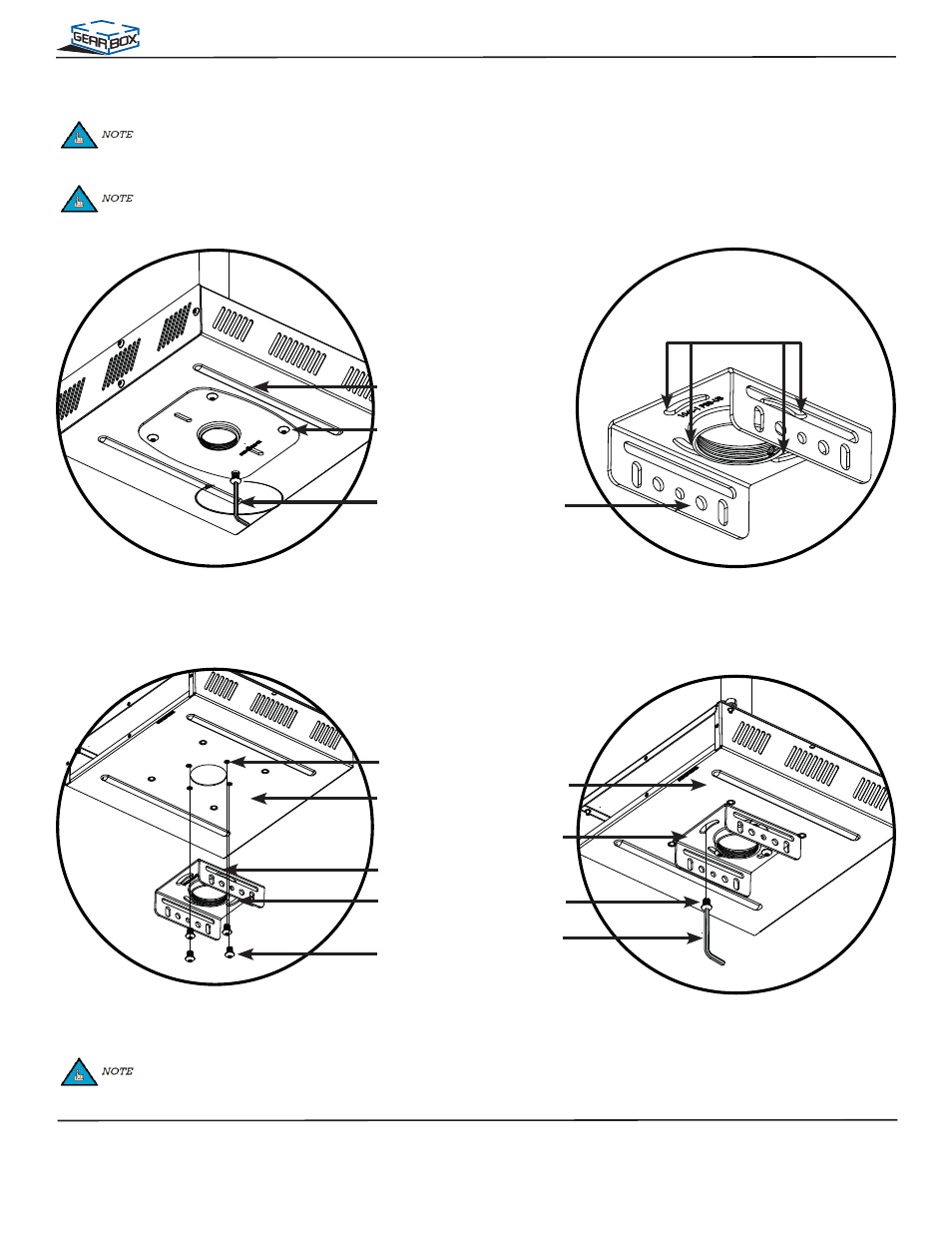
PDS-PLUS Installation without NPT (Optional)
Before attaching the PDS-PLUS, it is strongly recommended that all connections in the equipment tray be made at this
time. Once the connections are made, feed the cables through the plate hole and then through the 1-1/2” NPT. Please read
instructions below to complete the installation.
M5 Security
Wrench
M8 x 12mm
Security Head
Screw
Equipment
Tray
Step 1. Remove the lower mounting plate from
the equipment tray by removing the four
(4) M8 x 12mm security head screws with
an M5 security wrench.
Mounting Slots
Step 2. Locate the mounting slots that are on the
base box bridge of the PDS-PLUS.
Base Box
Bridge
Step 3. Line up the mounting slots on the base box
bridge with the mounting points on the
equipment
tray.
Step 4. Insert four (4) M5 x 10mm security screws
and tighten using the M5 security wrench.
M5 Security
Wrench
M5 Security
Wrench
M o u n t i n g
Point
Equipment
Tray
M5 x 10mm
Security Head
Screw
Equipment
Tray
Base Box
Bridge
Base Box
Bridge
Please refer to the PDS-PLUS Installation Instructions before proceeding with the following steps.
M5 x 10mm
Security Head
Screw
Be aware of the screen location and
orient the base accordingly.