Patton electronic 1193 User Manual
Page 5
7
lations and decodes them as zeros. This method enables the net-
work to meet minimum pulse density requirements. Use HDB3
unless AMI is required in your application.
Alternate Mark Inversion (AMI)
: AMI defines a pulse as a
“mark,” a binary one, as opposed to a zero. In an E1 Network con-
nection, signals are transmitted as a sequence of ones and zeros.
Ones are sent as pulses, and zeros are sent as spaces, i.e., no
pulse. Every other pulse is inverted from the previous pulse in
polarity, so that the signal can be effectively transmitted. This
means, however, that a long sequence of zeros in the data stream
will cause problems, since the modem receiving the signal relies
on the signal to recover the 2.048 Mbps clock.
If you must use AMI, ensure that the data terminal equipment con-
nected to the unit provides a minimally acceptable pulse density.
For this reason, there are advantages to using HDB3 instead. AMI
coding does not inherently account for ones density. To meet this
requirement, ensure that the data inherently meets pulse density
requirements.
S3
S4
DTE Line Coding
Off
Off
HDB3
On
Off
Internal use only
Off
On
Internal use only
On
On
AMI
Switches S5 through S8: Reserved
Switches S5 through S8 are reserved for future applications and
should be set to OFF.
3.1.2 Select RJ-48C or BNC Connectors
The Model 1193 is shipped configured for use with a BNC connec-
tion to the G.703/G.704 Network. If your Network connection is using
BNC, skip this section.
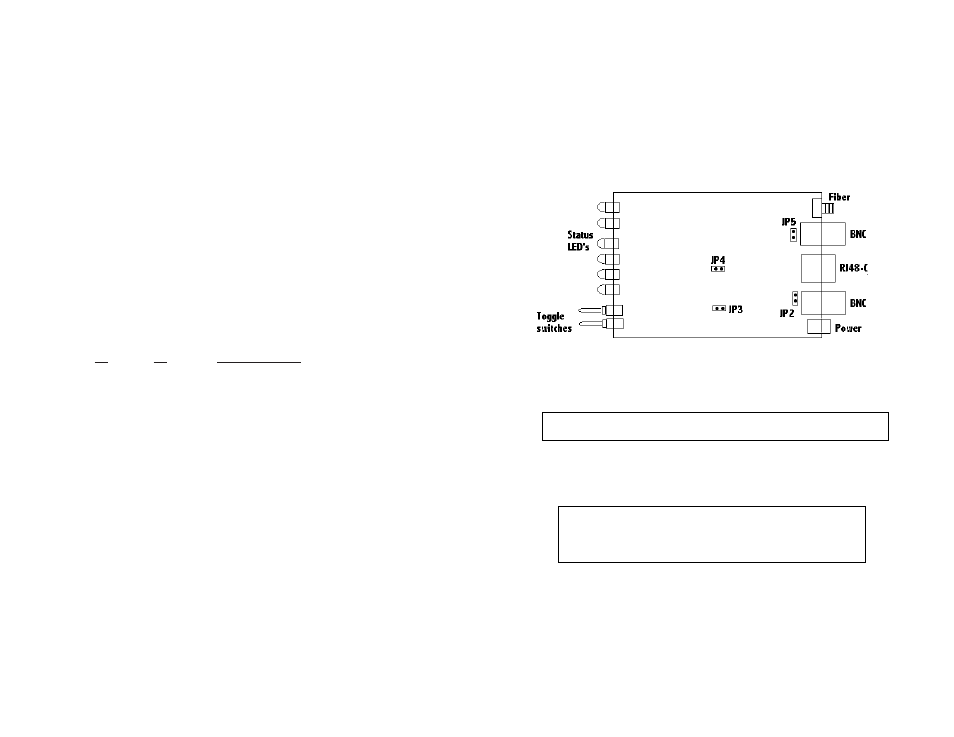
Jumper Configuration
The Model 1193 uses four internal jumpers: JP2, JP3, JP4, and
JP5 to match input/output impedance between the module and exter-
nal line on the G.703/G.704 interface. The jumper settings select either
a BNC (75-ohm) or an RJ-48C (120-ohm) interface. Figure 4 below
shows the top view of the printed circuit board (PCB) and the location
of the jumpers.
Open the Case
To open the case, insert a screwdriver into the slots and twist the
screwdriver head slightly. The top half of the case will separate from
the lower half of the case. Take caution not to damage any of the PC
board mounted components.
The following is a description of the jumper settings and the interface
selection:
1. For a 75-ohm connection (BNC/coax), insert jumpers JP2, JP3, JP4,
and JP5 (default).
2. For a 120-ohm connection (RJ-48C/twisted pair), remove jumpers
JP2, JP3, JP4, and JP5.
8
Figure 4:
Top view of 1193 circuit board and location of jumpers
Note: Electronic equipment is sensitive to ESD (electrostatic
discharge). When you change the internal jumpers on the
1193, use a grounding strap to avoid damages. For more
information call Patton Technical Support (301) 975-1007.
Note: When opening and closing the case, be sure not to damage the
fiber optic cable inside the unit.