Front rear – Patton electronic 1193 User Manual
Page 4
3
3..0
0 C
CO
ON
NF
FIIG
GU
UR
RA
AT
TIIO
ON
N
The Model 1193 is equipped with eight DIP switches, which allow
configuration of the unit for a wide variety of applications. This section
describes location of the switches and explains all possible configura-
tions.
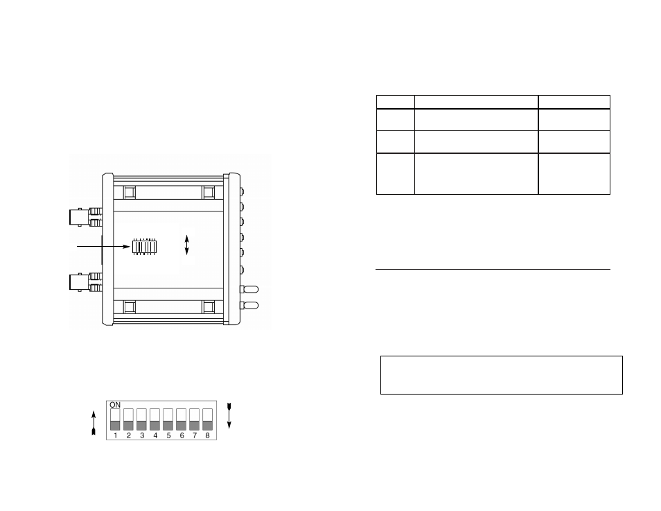
3.1 CONFIGURING THE HARDWARE DIP SWITCHES
The 8 external dip switches are accessible from the underside of
the Model 1193 (See Figure 2 below).
Figure 3 shows the orientation of the DIP switches in the
“ON” and “OFF” positions.
5
Figure 3.
Close up of configuration switches
Figure 2.
Underside of Model 1193, showing location of the DIP switches
Front
Rear
On
Off
3.1.1 Configure the Model 1193
Switches S1 through S8 may be used to configure clocking modes
and line coding. Default settings of the switches are shown in the table
below. A description of the switch options follows the table.
Switches S1 and S2: Clock Mode
Use switches S1 and S2 to determine clock mode of the 1193.
S1 S2 Setting Description
On
On
Internal
Transmit clock generated internally
On
Off
Receive Recover Transmit clock derived from the line
Off
On Network
Transmit clock derived from G.703/G.704
equipment interface
Off
Off
Internal use only
Switch S3 and S4: Line Coding Options
Use switches S3 and S4 to determine whether the G.703/G.704 line
coding is HDB3 or AMI (for older telecommunications equipment). The
line coding must be the same line coding prescribed by the NAP
(Network Access Provider). Most applications will use HDB3.
High Density Bipolar 3 (HDB3)
: In HDB3 coding, the transmitter
deliberately inserts a bipolar violation when excessive zeros in the
data stream are detected. The receiver recognizes these special vio-
6
OFF
ON
S1
Note: The Model 1193 units are intended to work in pairs. Set the clock
modes for the Model 1193 units with one end of the link set for receive
recover and the other end set for either internal or network.
Position
Function
Default Setting
S1
Clock Source
ON
S2
Clock Source
ON
S3
Line
OFF
S4
Coding
OFF
S5
S6
Reserved for Future Applications
OFF
S7
S8
}
}
Internal
Clock
HDB3