Connections, English – Philips DVD VIDEO/ SACD PLAYER DVP900SA/00_A User Manual
Page 11
/00_3139 246 13872
English
11
Connections
S-VIDEO
Y
Pb
Pr
COMPONENT
SCAN MODE
INTERLACE
PROGRESSIVE
VIDEO
VIDEO OUT
HDMI
PCM /
D
COAXIA
DIG
AV
Scan Mode
(Progressive/Interlace selector)
This switch will change the type of signal
output from the Component Video Out
on the DVD player.
Interlace:
Select this setting when connected to a
standard (interlace format) TV.
Progressive:
Select progressive when you have a TV
that can accept progressive signals (480/
525p) to enjoy accurate colour
reproduction and high quality images.
Helpful hints:
–
During Progressive mode, 4:3 aspect
images are distorted when TV Shape is set to
‘16:9’ . Change the TV screen’s aspect ratio
settings to AUTO to avoid image distortion.
(see page 31 “4:3 Aspect”).
–
Some TVs and projectors are not
compatible with this DVD Player. If picture
distorted during progressive signals, switch
the SCAN MODE to Interlace.
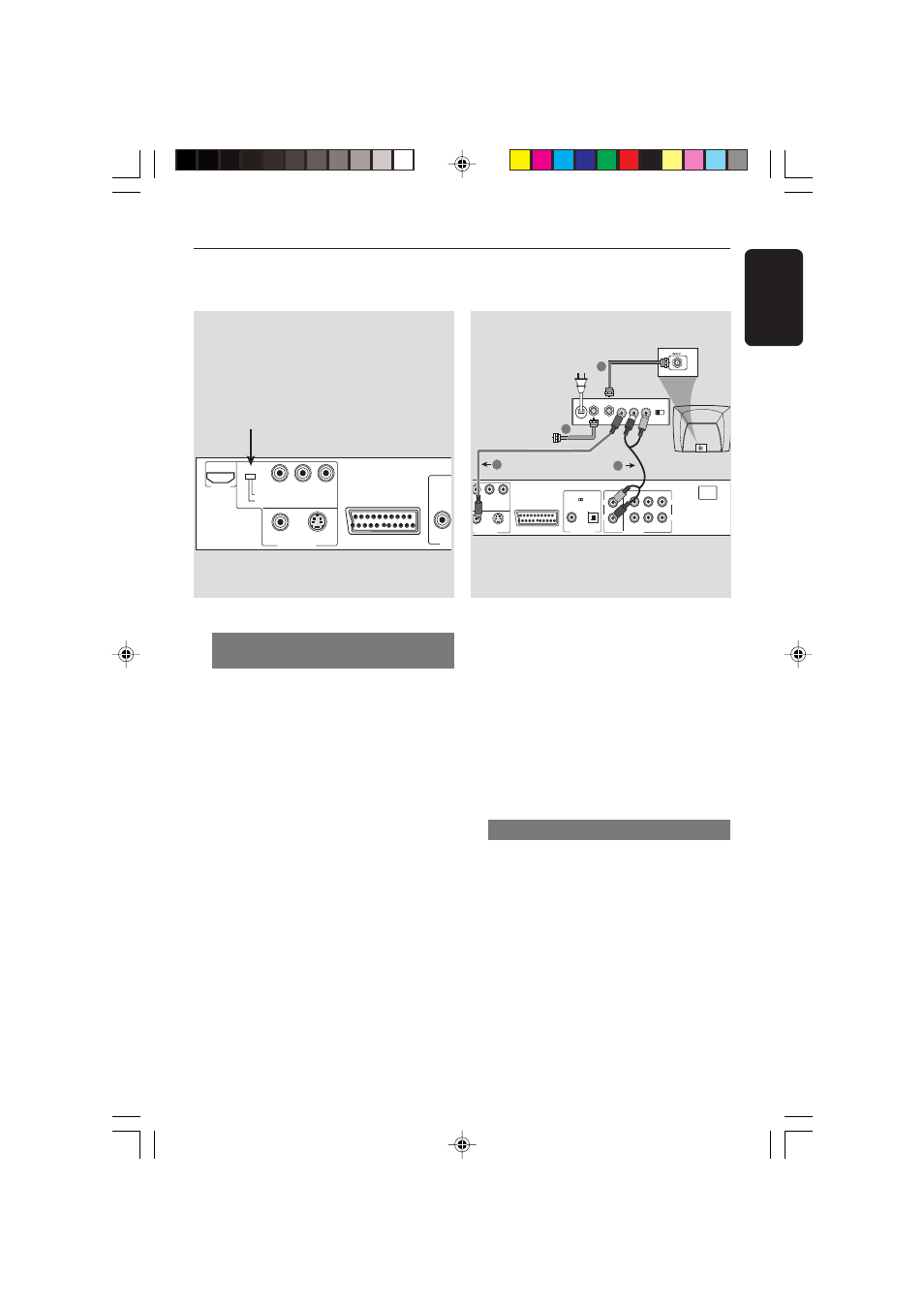
IMPORTANT!
– If your TV only has a single
Antenna In jack (labeled as 75 ohm
or RF In), you will need an RF
modulator in order to view DVD
playback on the TV. The RF
modulator is not supplied with the
DVD Player. See your electronics
retailer or contact Philips for details
on RF modulator availability and
operations.
Using an accessory RF modulator
1
Use the composite video cable (yellow) to
connect the DVD Player’s CVBS jack to
the video input jack on the RF modulator.
2
Use the RF coaxial cable (not supplied) to
connect the RF modulator to your TV’s
RF jack.
S-VIDEO
Y
Pb
Pr
MIXED 2CH
MAIN
CENTER
SUB WOOFER
6CH DISCRETE
SURROUND
L
L
R
L
R
COMPONENT
CE
SIVE
VIDEO
VIDEO OUT
PCM / DIGITAL/
DTS / MPEG
COAXIAL
OPTICAL
DIGITAL OUT
R
AUDIO OUT
~ AC
MAINS
AV
AUDIO IN
R L
VIDEO
IN
TO TV
ANT IN
CH3 CH4
3
1
2
4
ANT IN
RF coaxial cable to TV
Back of RF Modulator
(example only)
Antenna or
Cable TV signal
01-41 DVP900_00A1
15/09/2004, 10:00 AM
11