Assemble upstop bracket, Assemble wheels – Poulan 193747 User Manual
Page 10
10
ASSEMBLE UPSTOP
BRACKET
(SEE ILLUSTRATION ABOVE)
• Position upstop bracket over hole inside
the left side of upper handle and install
upstop bracket screw #10-24 x 1/2.
Tighten securely.
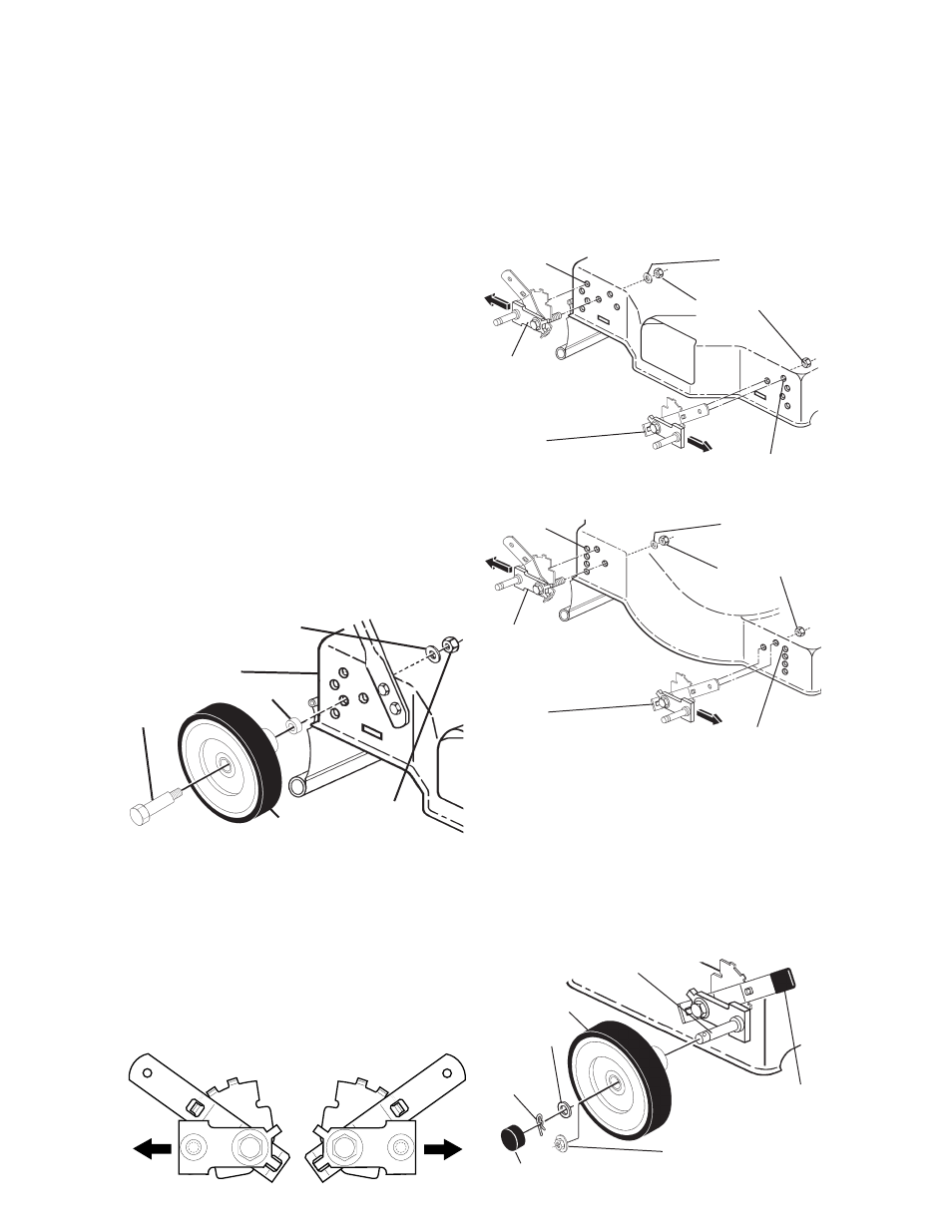
ASSEMBLE WHEELS
(USE HARDWARE GROUP “C”)
NOTE: Some model mowers do not have
baffl es on underside of mower housing.
On models without baffl e in front and/or
rear of housing, use the 1-1/4" washers
sup plied when you assemble the wheels.
MODELS WITH BOLT-ON WHEELS:
Cutting height is de ter mined by as sem -
bling wheels in one of four possible posi-
tions on the mower housing. All wheels
must be in the same height position for
even cut ting.
• For each wheel, assemble shoul der bolt,
wheel and spacer as shown.
• Assemble 1-1/4" diam. washer (if sup-
plied) and 3/8-16 lock nut on inside of
mower housing and tight en se cure ly.
(SIDE DISCHARGE MOWER SHOWN)
MODELS WITH "QUICK ADJUST"
WHEEL HEIGHT ADJUSTERS :
Look carefully at the four (4) adjuster
assemblies. Notice that there are two (2)
each of two (2) different types.
Spacer
Wheel
3/8-16
Locknut
1-1/4" diameter Washer
(Rear wheels only)
Mower housing
Shoulder
bolt
ASSEMBLE ADJUSTERS TO DECK
• Position appropriate adjuster at each
corner of mower.
• Install each adjuster with adjuster bolt
and tab in deck holes as shown and
secure with 1-1/4" diam. washer (if sup-
plied) and 3/8-16 locknut. Tight en all
adjusters se cure ly.
SIDE DISCHARGE MOWERS:
REAR DISCHARGE MOWERS:
ASSEMBLE WHEELS TO ADJUSTERS
• Secure each wheel with fl at washer
and retainer spring or fl ange locknut (if
equipped with threaded axle).
• Assemble adjustment knobs to ad just er
levers by press ing or tapping lightly.
• If your mower is equipped with hub caps,
install by pressing or tap ping lightly until
hub cap snaps se cure ly over fl at wash er.
Wheel
Flat washer
Retainer
spring
Axle arm
Hubcap (If epuipped)
Flange locknut
(If equipped with
threaded axle arm)
Adjustment
knob
Type I is for the
Right Rear and Left
Front installation.
Type II is for the
Right Front and Left
Rear installation.
TYPE I
Right rear/left front
height ad just er
TYPE II
Right front/left rear height ad just er
Tab hole
Tab hole
1-1/4" Washer
(If supplied)
Locknuts
TYPE I
Right rear/left front
height ad just er
TYPE II
Right front/left rear height ad just er
Tab hole
Tab hole
1-1/4" Washer
(If supplied)
Locknuts