Connecting power, Grounding the model sn4400-ac and dc units, Grounding the model sn4400—ac and dc units – Patton electronic SmartNode 4400 User Manual
Page 30: Db-9-to-rj-45 cable diagram, Connecting the eia-561 rs-232 configuration port, Dce configured)
Installing the IpChannel Bank
30
SmartNode 4400 Series Getting Started Guide
3 • Hardware installation
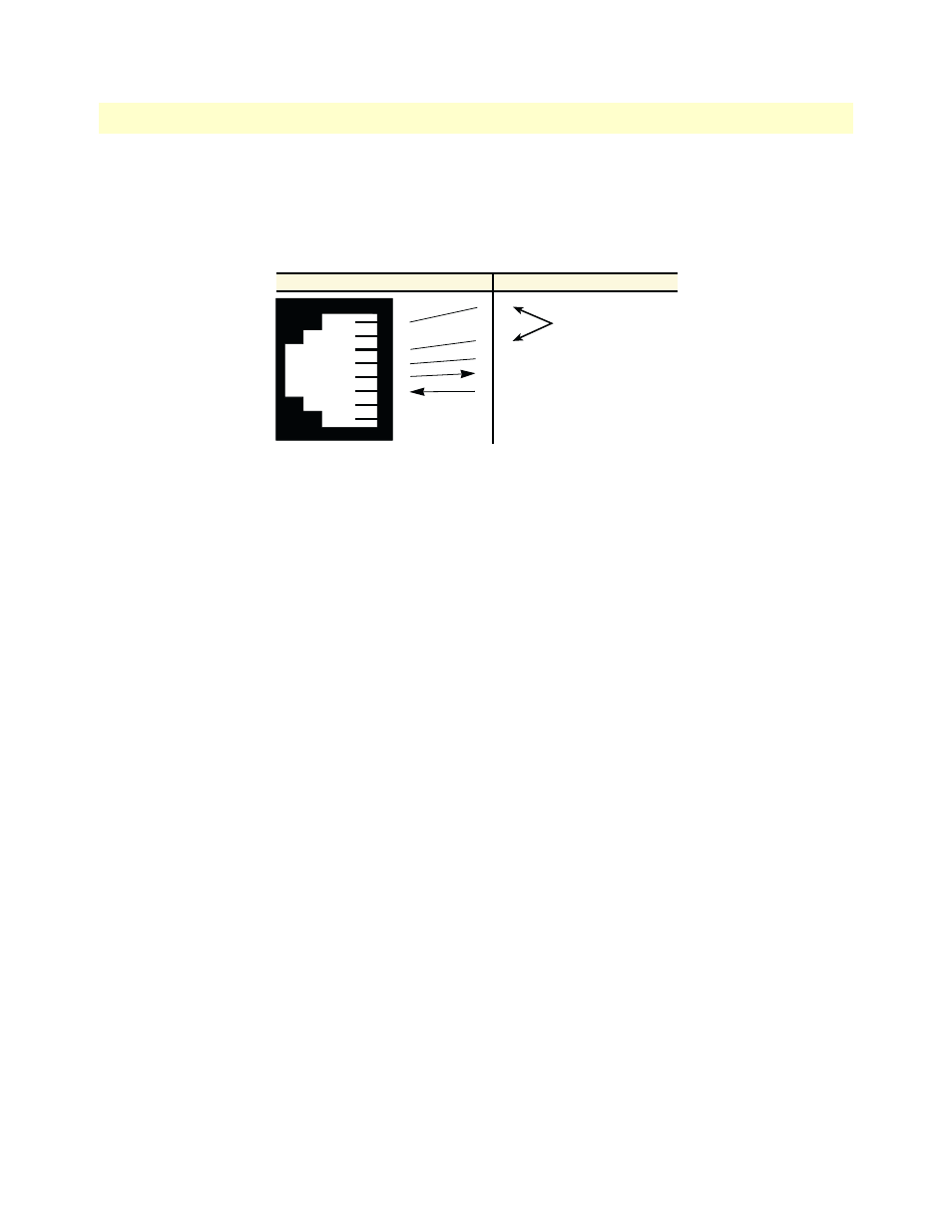
Connecting the EIA-561 RS-232 configuration port (DCE configured)
Install the supplied RJ-45-to-RJ-45 cable with the DB9-RJ45 adapter between the SN4400 IpChannel Bank
RS-232 console port (
) and an open serial port on your computer. If you need to assemble your own
cable, refer to the pinout diagram in
.
Figure 10. DB-9-to-RJ-45 cable diagram
Connecting power
In connecting to the power source, it is important to establish a good grounding connection first, then the
power connection. This section explains:
•
Making the ground connection for either AC or DC units (see section
•
Connecting to an AC power source (see
“Installing the power cables—AC units”
•
Connecting to a DC power source (see
“Installing the power cables—DC units”
Grounding the Model SN4400—AC and DC units
Do the following:
1. Assemble a ground wire using #10 AWG wire with green-colored insulation and two ring terminals. Make
the wire long enough to reach one of the following earth ground sources:
– The building ground rod (generally located at the site’s main service entrance)
– A sprinkler system pipe
– A cold-water pipe
– Building structural steel
6 DSR
1 CD
4 DTR
5 SG
2 RD (driven)
3 TD (received)
8 CTS
7 RTS
1
2
3
4
5
6
7
8
DSR & DTR are internally
wired together
RJ-45 Jack
Signal Name
DB-9