Patton electronic 1180 User Manual
Page 7
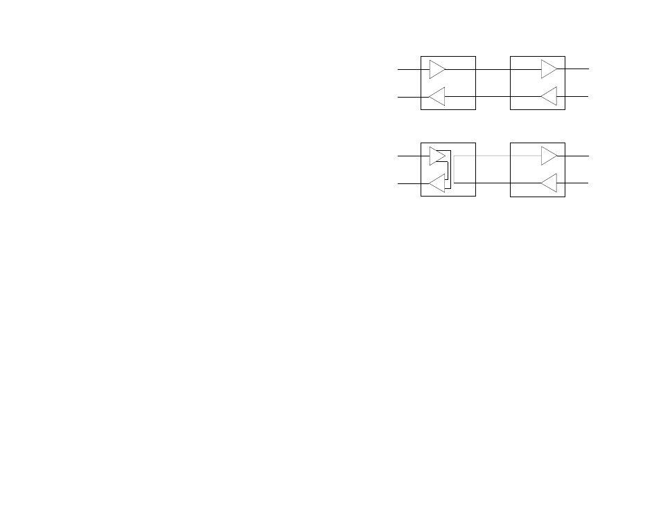
A. Activate local loopback by moving the front panel toggle switch
DOWN to “Local”. Once local loopback is activated, the Model 1180
transmit output is connected to its own receiver. The “test” LED should
glow. Note: Even though the local Model 1180 cannot communicate
with the remote Model 1180 in this mode, the synchronized connection
between the two modems remains intact.
B. Verify that the data terminal equipment is operating properly and
can be used for a test. If a fault is indicated, call a technician or replace
the unit.
C. Perform a BERT (bit error rate) test on each unit. If the BERT
test equipment indicates no faults, and the data terminal indicates a
fault, follow the manufacturer’s checkout procedures for the data
terminal. Also, check the RS-232 interface cable between the terminal
and the Model 1180.
5.3.2 REMOTE LOOPBACK
The remote loopback test checks the performance of both the local
and remote Model 1180s,
and
the communication link between them
(Figure 7). Any characters sent to the remote Model 1180 in this test
mode will be returned back to the originating device. For example,
characters typed on the keyboard of the local terminal will appear on
the local terminal screen
after
having been passed to the remote Model
1180 and looped back. To perform a remote loopback test, follow these
steps:
A. Activate remote loopback by moving the front panel toggle switch
UP to “Remote”. The “test” LED should glow.
B. Perform a BERT (bit error rate) test on the system.
C. If the BERT test equipment indicates a fault, and the local
loopback test was successful for both Model 1180s, this suggests a
problem with the fiber communication line connecting the modems. You
should then test the fiber line for proper connections and continuity.
5.4 POWER-DOWN
Turn off the Model 1180 by simply unplugging the AC power adapter
from the wall. There is no power switch on the Model 1180.
11
12
RD
TD
TD
RD
Local 1070RC
In Normal Mode
Remote 1070RC
In Normal Mode
TX+
TX-
RX-
RX+
RX+
RX-
TX-
TX+
RD
TD
TD
RD
Local 1070RC
In Loopback Mode
Remote 1070RC
In Normal Mode
RX+
RX-
TX-
TX+
TX+
TX-
RX-
RX+
RD
TD
TD
RD
Local 1080RC
In Normal Mode
Remote 1080RC
In Normal Mode
TX+
TX-
RX-
RX+
RX+
RX-
TX-
TX+
RD
TD
TD
RD
Local 1080RC
In Loopback Mode
Remote 1080RC
In Normal Mode
RX+
RX-
TX-
TX+
TX+
TX-
RX-
RX+
RD
TD
TD
RD
Local 1180RC
In Normal Mode
Remote 1180RC
In Normal Mode
TX
RX
RX
TX
RD
TD
TD
RD
Local 1180RC
In Loopback Mode
Remote 1180RC
In Normal Mode
RX
TX
TX
RX
Figure 7. Local and remote loopback test modes