Patton electronic 1180 User Manual
Page 3
3.0 CONFIGURATION
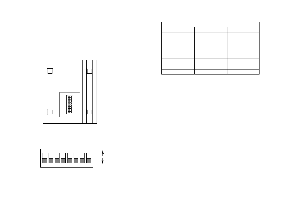
The Model 1180 uses a set of eight external DIP switches that
allow configuration to a wide range of applications. Because all eight
switches are in one externally accessible DIP package, there is no need
to open the Model 1180’s case for configuration. The switches allow
you to control data rates and clocking methods. Figures 1, 2 and 3
summarize the switch locations, positions and functions.
3
4
1
2
3
4
5
6
7
8
ON
FRONT
REAR
1
2
3
4
5
6
7
8
ON
OFF
ON
3.1 DETAILED SWITCH SETTINGS
This section provides detailed information about the function of
each DIP switch and lists all possible settings. Use this section as
configuration guide for applications where the Model 1180’s default
would not provide correct results.
Switch 1: Reserved for Future Use
Switches 2 though 5: Data Rate (Sync. Mode)
Switches 2 through 5 determine two configuration parameters:
synchronous or asynchronous data rate and the mode of
synchronization (Sync. Mode) between two Model 1180s. The “Sync.
Mode” setting (active in both asynchronous and synchronous operating
modes) defines the packet length of the data stream between the two
Model 1180s.
Simply put, the “2X” setting doubles the space between data
packets when compared with the “1X” setting. A Sync. Mode setting of
“2X” facilitates communication distances up to 5 Km. A Sync. Mode
setting of “1X” limits communication distances to 2.5 Km. The following
table shows every possible data rate/Sync. Mode switch setting for the
Model 1180.
SWITCH SUMMARY TABLE
Position
Function
Factory Default
Switch 1
RESERVED
Off
Switch 2
Data Rate (Sync Mode)
On
Switch 3
Data Rate (Sync Mode)
Off
Switch 4
Data Rate (Sync Mode)
Off
Switch 5
Data Rate (Sync Mode)
On
Switch 6
Reset
Off
Operating Mode
Switch 7
Handshaking
On
Control Signal Mode
Switch 8
Clocking Method
Off
Internal Clock
0 - 19.2
Async (2x)
}
Figure 1. Switch locations underneath Model 1180
Figure 2. Close up of 1180 DIP switch package showing OFF/ON positions.
Figure 3. Summary of switch settings, showing factory defaults