Warning, Made in china by sunny – Patton electronic 1186 User Manual
Page 7
11
4.3 POWER CONNECTION
4.3.1 Universal AC Power (100-240VAC)
The Model 1186 uses a 5VDC, 2A universal input 100-240VAC,
power supply (center pin is +5V). The universal input power supply
has a male IEC-320 power entry connector. This power supply con-
nects to the Model 1186 by means of a barrel jack on the rear panel.
Many international power cords are available for the universal power
supply (Please refer to Appendix B for country-specific power cords).
The Model 1186 powers up as soon as it is plugged into an AC
outlet. The unit does not have a power switch.
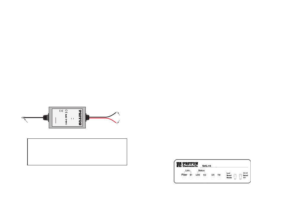
4.3.2 DC Power
The 36-60 VDC DC to DC adapter is supplied with the DC version
of the Model 1186. The black and red leads plug into a DC source
(nominal 48VDC) and the barrel power connector plugs into the barrel
power supply jack on the rear panel of the 1186. (See Figure 9).
Figure 9.
Connect DC power to the 48V-PSM3 DC power supply
WARNING!
There are no user-serviceable parts in the
power supply section of the Model 1186. Fuse replacement
should only be performed by qualified service personnel.
Contact Patton Electronics Technical Support at (301) 975-
1007, via our web site at http://www.patton.com, or by e-mail
at [email protected], for more information.
5
5..0
0 O
OP
PE
ER
RA
AT
TIIO
ON
N
Once the Model 1186 is properly configured and installed, it should
operate transparently. This section describes power-up, reading the
LED status monitors, and using the built-in loopback test modes.
5.1 POWER-UP
To apply power to the Model 1186, first be sure that you have read
Section 4.3, and that the unit is connected to the appropriate power
source.
Next, make sure that front panel switches are set to Normal condi-
tion. Then, plug provided power adapter (see section 4.3) first into the
rear panel outlet of the Model 1186, and then into the acceptable power
outlet (AC or DC depending on the model -UI or -DC). After both the
local and remote Model 1186s are powered up, a synchronization
process will occur to establish a link. The synchronization process
should take only a few seconds (<5 sec). Any time one of the Models
1186 loses power (i.e., in a lightning storm), the local and remote units
will re-synchronize before they can resume data transmission.
When the local and remote units have established a link and are
passing reliable data, the following LED conditions will exsit:
· Fiber = GREEN
· E1 = GREEN
· LOS = OFF
· NS = OFF
· ER = OFF
· TM = OFF
5.2 LED STATUS MONITORS
The Model 1186 features six front panel status LEDs that indicate
the condition of the modem and communication link. Figure 10 shows
the front panel location of each LED.
12
Figure 10.
Model 1186 front panel
Multi-Mode Fiber G.703/G.704 Modem
To Power
Supply Jack
To -48VDC
Source
-Vin
+Vin
SWITCHING POWER SUPPL
Y
MODEL
: SYD1
106-0505
INPUT
: 36-60V 0.2A
MAX
OUTPUT
: +5V 1.0A
OUTPUT
POWER : 5W MAX
S/N
: G01234567890
MADE IN CHINA
BY
SUNNY
Black lead (-V)
Red lead (+V)
Barrel power connector