Network – Patton electronic 1186 User Manual
Page 6
9
4
4..0
0 IIN
NS
ST
TA
AL
LL
LA
AT
TIIO
ON
N
Once the Model 1186 is properly configured, it is ready to connect
to the fiber interface, to the G.703/G.704 equipment, and to the power
source. This section describes how to make these connections.
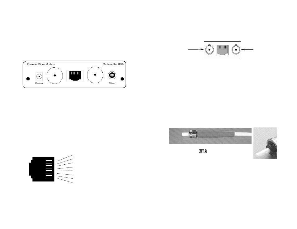
The power, G.703/G.704 and Fiber Line connections are located
on the rear panel of the Model 1186. Figure 5, below, shows the loca-
tion of each of these ports.
4.1 CONNECT THE G.703/G.704 NETWORK
There are two ways to connect to the G.703/G.704 Network. This
section describes both options. After selecting the appropriate connec-
tion, set the internal jumpers as described in section 3.1.2 of this man-
ual.
4.1.1 Connect Twisted Pair (120 Ohm) to G.703/G.704 Network
The Model 1186 is equipped with a single RJ-48C jack option for
connections to a G.703/G.704 Network. If your G.703/G.704 Network
terminates via an RJ-48C, use the diagram below (Figure 6).
4.1.2 Connect Coax Cable to the G.703/G.704 Network
The Model 1186 is also equipped with dual female BNCs (TX and
RX) for connection to a 75 ohm dual coax G.703/G.704 Network inter-
face. If your G.703/G.704 Network terminates via dual coaxial cable,
10
use the diagram below to make the proper connections. The connec-
tor pinout and signals are shown in Figure 7, below.
4.2 CONNECT THE FIBER INTERFACE
The Model 1186 is designed to be connected to another Model
1186. The Model 1186 supports communication between G.703/G.704
equipment over one string of multi-mode fiber at distances up to 2.5
km (1.5 miles). One modem can connect to another on the end of a
single string of fiber optic cable.
To connect two Model 1186s, use one string of 62.5/125 micron
multi-mode fiber. The fiber connects to each Model 1186 using either
an ST or an SMA connector.
Figure 8 below shows a close-up of both connector types.
Figure 5.
G.703/G.704 Interface and power connection ports
RX
(Data
FROM
G.703/G.704
Network)
TX
(Data
TO
G.703/G.704
Network)
Network
Figure 7.
Fiber cable to G.703/G.704 Interface connection
G.703/G.704
Figure 6.
G.703/G.704 Network Interface.
1 RX Data (TIP)
2 RX Data (RING)
3 (no connection)
4 TX Data (TIP)
5 TX Data (RING)
6 (no connection)
7 (no connection)
8 (no connection)
1
2
3
4
5
6
7
8
Figure 8:
Model 1186 SMA and ST multi-mode fiber connectors
}
}
From Network
To Network