2 models with internal ac power supply, 3 models with internal dc power supply, 4 power-up indication – Patton electronic 2620 User Manual
Page 3: 0 configure the ip address, 1 connecting a pc and logging in
IPLink 2603 & 2620 Quick Start Guide
3
2.
Connect the barrel-type connector of the AC adaptor to the barrel-type
Power
jack on the IPLink router.
3.
Insert the male plug of the AC power cord into an AC power outlet (100–240 VAC).
1.2 Models with internal AC power supply
1.
Insert the female end of the AC power cord into the internal power supply connector.
2.
Connect the male end of the power cord into an AC power outlet (100–240 VAC).
1.3 Models with internal DC power supply
1.
Strip insulation 1/4-inch from the electrical wires that will connect the DC power source to the IPLink.
2.
Connect the positive (+) terminal from the power source to the positive (+) terminal on the IPLink.
3.
Connect the ground terminal from the power source to the ground terminal (E) on the IPLink.
4.
Connect the negative (-) terminal from the power source with to the negative (-) terminal on the IPLink.
Figure 1.
Connecting the DC power supply
Note
“+”, “E”, and “-” may be unlabeled.
1.4 Power-up indication
The
Power
LED blinks as the IPLink is powering up. When the
Power
LED stops blinking and remains lit, the
IPLink is ready for you to configure.
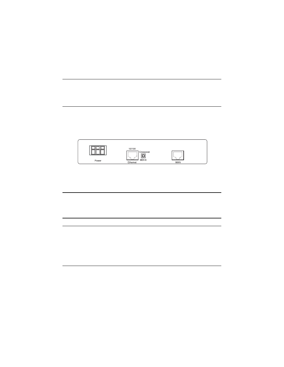
2.0 Configure the IP address
The IPLink is shipped with a factory-configured IP address assigned to the
Ethernet
LAN port (green outline). The
address is
192.168.200.10/24
. In most cases, you must change the address to be on the same subnet as your
PC, as described in the procedures below. If you are not sure which IP address to use for your installation, contact
your network administrator.
2.1 Connecting a PC and logging in
1.
Using the included combination RS232/Ethernet cable and DB9-RJ45 adapter, connect a PC’s serial port
to the IPLink’s
Console
port (see
figure 2
).
+
E
-