Appendix a networking connection, A.1 switch‘s rj-45 pin assignments, A.2 rj-45 cable pin assignment – Planet Technology POE-151 User Manual
Page 10
- 10 -
APPENDIX A NETWORKING CONNECTION
A.1 Switch‘s RJ-45 Pin Assignments
RJ-45 Connector pin assignment
Contact
MDI
Media Dependant In-
terface
MDI-X
Media Dependant In-
terface -Cross
1
TX + (transmit)
Rx + (receive)
2
TX - (transmit)
Rx - (receive)
3
Rx + (receive)
TX + (transmit)
4, 5
DC current*
6
Rx - (receive)
TX - (transmit)
7, 8
Ground
Remark:
Gigabit Ethernet is not allowed to use POE-151 since pair 4,5 and pair 7, 8 are all being used for data transmission in
Gigabit Ethernet data transmission. Only 10Base-T and 100Base-TX can apply with POE-151 products.
A.2 RJ-45 cable pin assignment
2 1
3
6
1
2
3
6
2 1
3
6
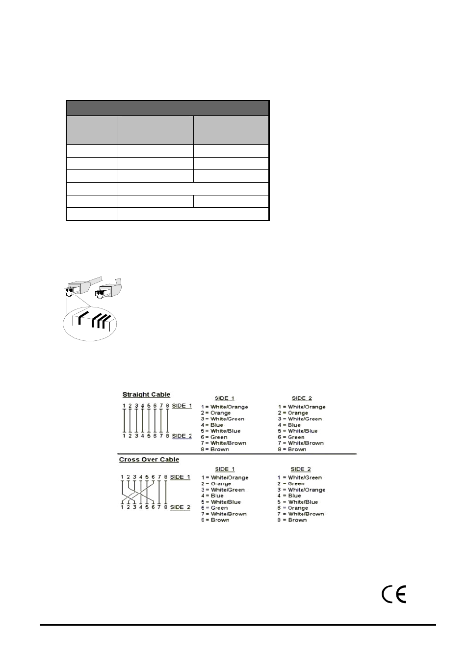
The standard RJ-45 receptacle/connector
There are 8 wires on a standard UTP/STP cable and each wire is color-coded. The following shows the pin allocation and
color of straight cable and crossover cable connection:
Figure A-1: Straight-Through and Crossover Cable
Please make sure your connected cables are with same pin assignment and color as above picture before deploying the
cables into your network.
2080-A31120-000