Philips CE130 User Manual
Page 9
10
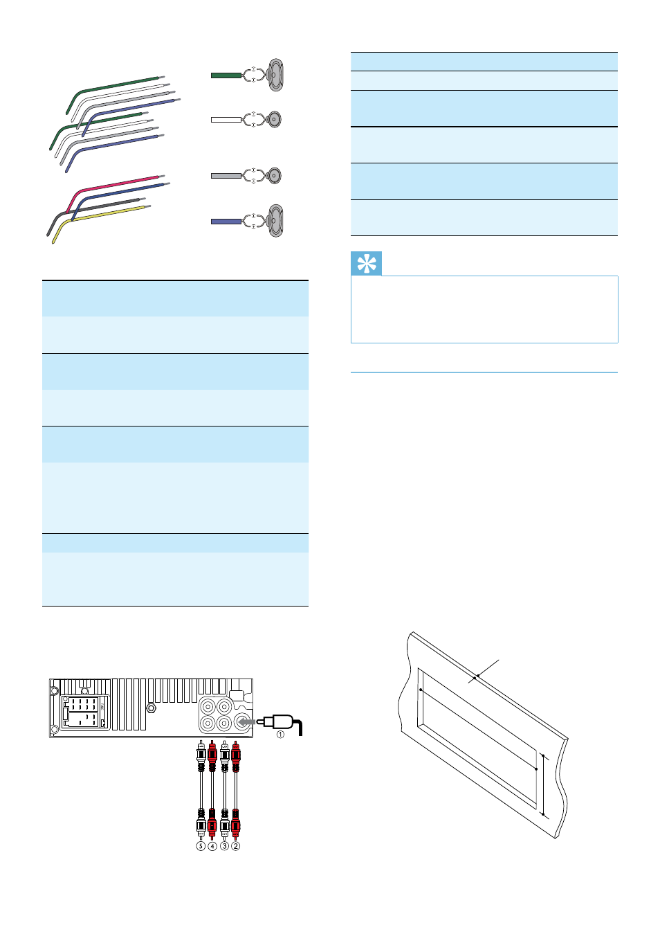
Connector
Connect to
1
ANTENNA
Antenna
2
FRONT LINE OUT
R (Socket)
Front right
speaker
3
FRONT LINE OUT
L (Socket)
Front left
speaker
4
REAR LINE OUT R
(Socket)
Rear right
speaker
5
REAR LINE OUT L
(Socket)
Rear left
speaker
Tip
The pin arrangement for the ISO connectors
•
depends on the type of vehicle you drive. Be
sure to make proper connections to prevent
damage to the unit.
Mount into the dashboard
1
If the car does not have an on-board
drive or navigation computer, disconnect
the negative terminal of the car battery.
If you disconnect the car battery in
•
a car that has an on-board drive or
navigation computer, the computer
may lose its memory.
If the car battery is not disconnected,
•
to avoid short-circuit, ensure that the
bare wires do not touch each other.
2
Ensure that car dashboard opening is
within these measurements:
183 mm
53mm
5mm
1
Green/
black strip
Left speaker (Rear)
2
White/
black strip
Left speaker (Front)
3
Gray/black
strip
Right speaker (Front)
4
Purple/
black strip
Right speaker (Rear)
e
Red
Ignition key +12V DC
when ON/ACC
f
Blue
Motor/electric antenna
relay control lead/
Amplifier relay control
lead
g
Black
Ground
h
Yellow
To the +12V car
battery which is
energized at all times
3
Connect the antenna and amplifier as
illustrated, if applicable.
b
a
c
d
a
a
b
c
d
a
b
e
f
c
d
g
h
b
c
d
L
R
Rear
Front
EN