Peavey SMRTM 821a User Manual
Page 7
7
IIn
nsstta
alllla
attiio
on
n
C
Co
on
nn
ne
eccttiio
on
nss
The SMR™821a is designed to be installed in a standard EIA equipment rack. Since the depth of the
unit is only 8
3
⁄
4
"‚ you can use practically any size rack. Using only a single EIA rack space‚ the SMR
821a includes integral rack mounting ears and does not require any additional hardware for rack
mounting…other than rack screws!
All connections are made on the rear panel. It is recommended that you provide an additional 4" of
clearance between the rear of the chassis and the interior rear of your equipment rack for wiring
harnesses. Since every connection to the SMR 821a is easy to disconnect‚ the unit can be removed
from an equipment rack easily‚ without having to disturb fixed wiring harnesses.
Using common sense when installing this unit will help ensure that it will provide years of trouble-
free service. In installations where there are multiple power amplifiers‚ it is also recommended that
the SMR 821a be located more towards the top of the rack‚ while power amplifiers remain near the
bottom. This is generally considered standard rack design in the commercial audio industry. Following
this convention will ensure adequate rack cooling‚ proper weight distribution and reliable operation
from the SMR 821a.
Connecting the SMR 821a is not much different than any other analog audio device. In addition to the
normal inputs and outputs‚ there are also external control ports and bus link connectors.
N
No
otte
e:: A
Allll cca
ab
blle
ess ffo
orr tth
he
esse
e cco
on
nn
ne
eccttiio
on
nss ssh
ho
ou
ulld
d b
be
e ssh
hiie
elld
de
ed
d.. R
Re
effe
err tto
o tth
he
e ffo
ollllo
ow
wiin
ng
g
iillllu
ussttrra
attiio
on
nss ffo
orr e
ea
acch
h tty
yp
pe
e o
off cco
on
nn
ne
eccttiio
on
n..
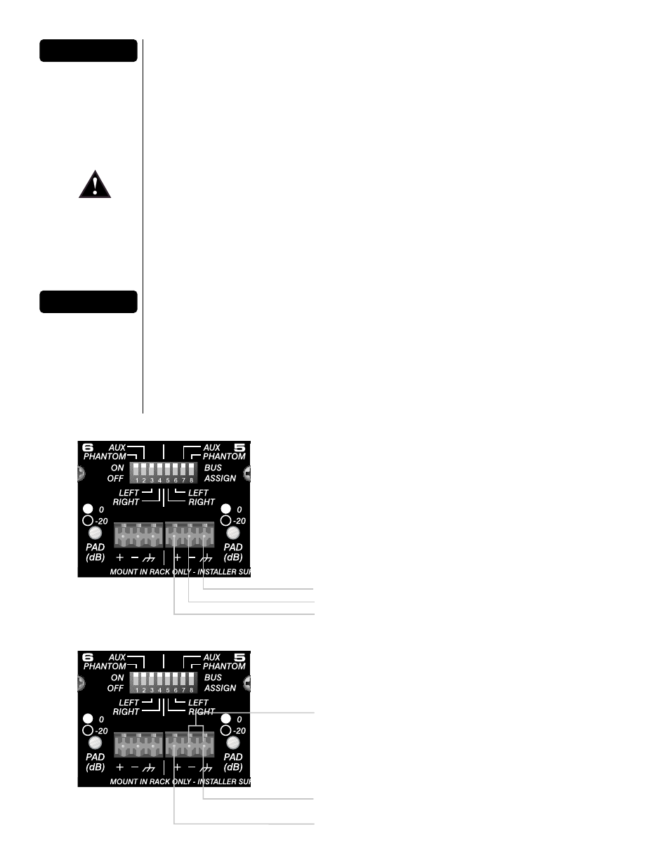
Audio Inputs
The inputs to the SMR 821a are balanced. This means there are three wires for each connection:
positive; negative and shield. These should be connected to each pin accordingly.
Figure 1. Balanced Audio Input Connections: Microphone or Line Level
Shield
Audio Negative
Audio Positive
Insert jumper wire between the negative and shield
pins for unbalanced circuits
Figure 2. Unbalanced Audio Input Connections: Microphone or Line Level
Shield
Audio “Hot” or Positive