Operational controls and adjustments, Start/stop controls, Locking switch in the “off” position – Porter-Cable 70-200 User Manual
Page 15: Spindle speeds, Changing spindle speeds and belt tension, Operation
15
OPERATIONAL CONTROLS AND ADJUSTMENTS
Fig. 23
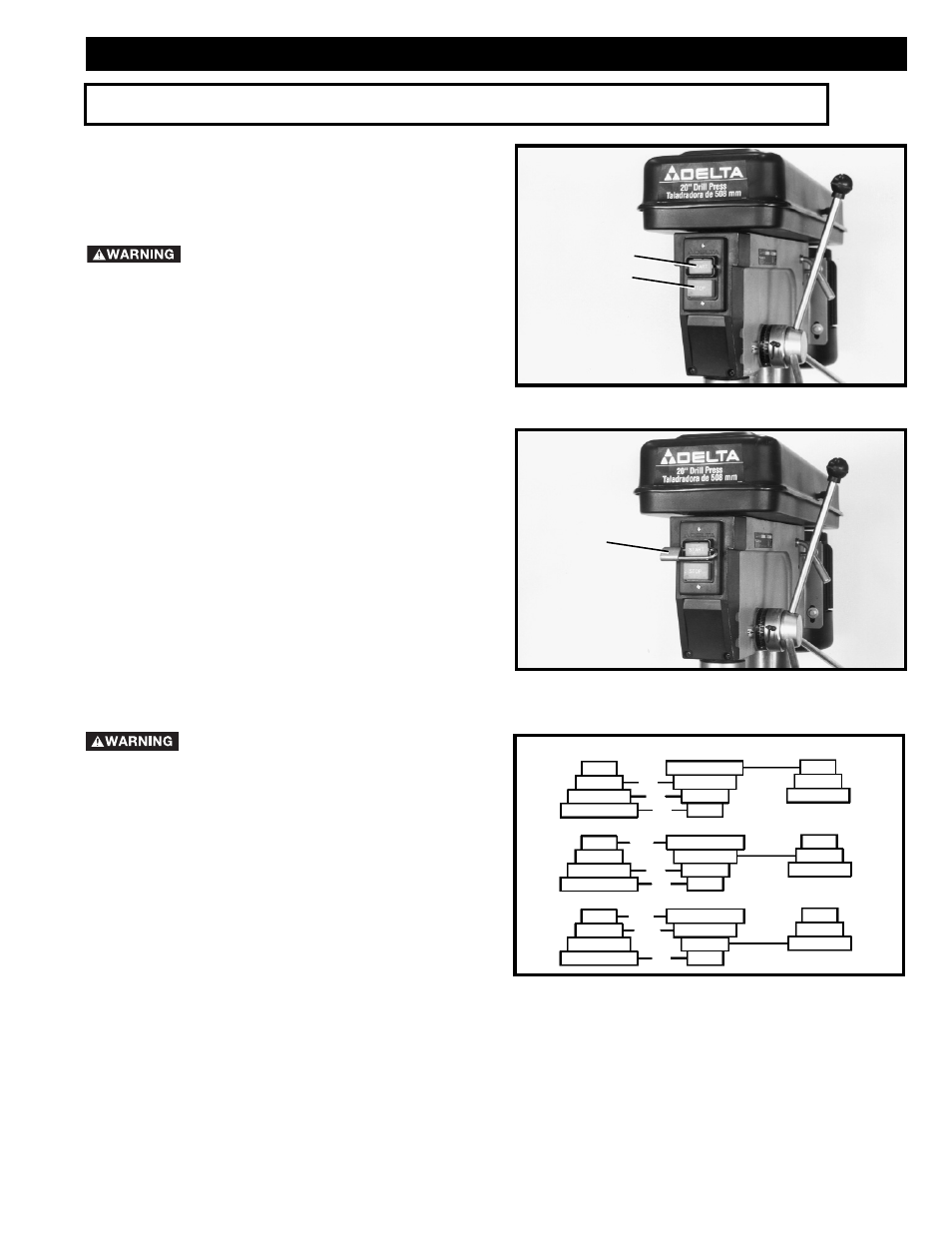
START/STOP CONTROLS
The start/stop buttons are located on the front of the drill
press head. To start the machine, press the start button (A)
Fig. 23, and to stop the machine, press the stop button (B).
MAKE SURE THAT THE BUTTON IS IN
THE “STOP” POSITION BEFORE PLUGGING IN THE
POWER CORD. IN THE EVENT OF A POWER FAILURE,
PUSH THE “STOP” BUTTON. AN ACCIDENTAL START-
UP CAN CAUSE INJURY.
LOCKING SWITCH IN
THE “OFF” POSITION
IMPORTANT: When the machine is not in use, the
“STOP” button should be locked to prevent
unauthorized use, using a padlock (C) Fig. 24, with
3/16
″ diameter shackle.
Fig. 24
SPINDLE SPEEDS
Nine spindle speeds of 150, 260, 300, 440, 490, 540,
1150, 1550, and 2200 RPM are available with the 20
″
Drill Press. Fig. 25, illustrates which steps of the pulleys
the belts must be placed to obtain the nine speeds
available.
A
B
C
Fig. 25
SPINDLE
CENTER
MOTOR
440
300
150
1150
540
260
2200
1550
490
CHANGING SPINDLE
SPEEDS AND BELT TENSION
DISCONNECT MACHINE FROM THE
POWER SOURCE.
1.
Lift up the belt and pulley guard (A) Fig. 26.
2.
Loosen the two lock knobs, one of which is shown
at (B) Fig. 26. The remaining lock knob is located on the
opposite side of the head casting.
3.
Release belt tension by moving tension lever (C)
Fig. 26, forward.
4.
Position the two belts (D) Fig. 26, on the desired
steps of the motor, center and spindle pulleys. To raise
or lower motor pulley (E) Fig. 26, use the 4mm hex
wrench and loosen set screw (F), located under the
pulley. After pulley is positioned, re-tighten set screw (F).
OPERATION