Fx-301, I/o circuit and wiring diagrams, Npn output type pnp output type – Panasonic Digital Fiber Sensor FX-301 User Manual
Page 19
86
FX-301
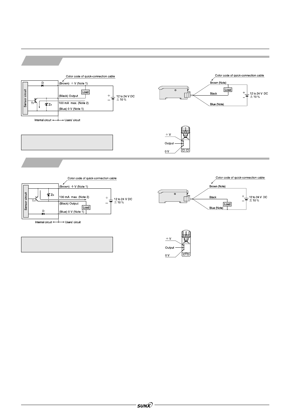
I/O CIRCUIT AND WIRING DIAGRAMS
I/O circuit diagram
Wiring diagram
Notes: 1) The quick-connection sub cable does not have
ם
V (brown) and 0 V (blue).
Notes:
2) 50 mA max., if five amplifiers, or more, are connected together.
Symbols … D : Reverse supply polarity protection diode
Z
D
: Surge absorption zener diode
Tr : NPN output transistor
Terminal arrangement diagram
NPN output type
PNP output type
Note: The quick-connection sub cable does not have brown lead wire
and blue lead wire.
I/O circuit diagram
Wiring diagram
Notes: 1) The quick-connection sub cable does not have
ם
V (brown) and 0 V (blue).
Notes:
2) 50 mA max., if five amplifiers, or more, are connected together.
Symbols … D : Reverse supply polarity protection diode
Z
D
: Surge absorption zener diode
Tr : PNP output transistor
Terminal arrangement diagram
Note: The quick-connection sub cable does not have brown lead wire
and blue lead wire.
08/2005