Commands, Cr> = carriage return (enter button) – Panamax 7500-PRO User Manual
Page 11
USA & Canada (800) 472-5555 • (707) 283-5900 • Fax (707) 283-5901
9
MAX PRO-SERIES Communication/Configuration Specifications
1. OVERVIEW
The M7500-PRO has a RS232 interface that allows it to communicate with a wide variety of equipment as well as enable custom
operating configurations to be programmed into the unit.
The purpose of this document is to outline the command set used to communicate with the M7500-PRO.
Commands and responses are in the form of ASCII character strings terminated with ASCII 13, line feed (ASCII 10) or NULL (ASCIØ).
Command String
Action
Response
Changes the status of the front panel button to ON.
Has the same effect as if someone pressed the front
panel button for 2 seconds.
Changes the status of the front panel button to OFF.
Has the same effect as if someone pressed the front
panel button for 2 seconds.
Turns off all outlets including those designated as
always on. Turn off is immediate with no delay.
Terminates any running turn on or turn off sequence.
Overrides the DC trigger input.
Changes the status of the front panel button to OFF.
Turns on all outlets. Turn on is immediate with no delay.
Terminates any running turn on or turn off sequence.
Overrides the DC trigger input.
Changes the status of the front panel button to ON.
Turns a specific outlet bank or the trigger output on or
off. Switching is immediate with no delay.
1.1
!BUTTON_ON
1.2
!BUTTON_OFF
1.3
!ALL_OFF
1.4
!ALL_ON
1.5
!SWITCH bank state
bank = {1, 2, 3, 4, HC1, HC2,
TRIGOUT}
state = {ON, OFF}
Example: !SWITCH 2 ON
(turns on outlet bank 2)
$BUTTON = ON
$BUTTON = OFF
$BUTTON = OFF
If successful: $BUTTON = ON
If over-voltage fault: $PWR = OVERVOLTAGE
If under-voltage fault: $PWR = UNDERVOLTAGE
If bank or state are invalid, $INVALID_PARAMETER
If bank and state are valid, and no fault exists, a
confirmation message is sent. Refer to §3.1
If over-voltage fault:$PWR = OVERVOLTAGE
If under-voltage fault: $PWR = UNDERVOLTAGE
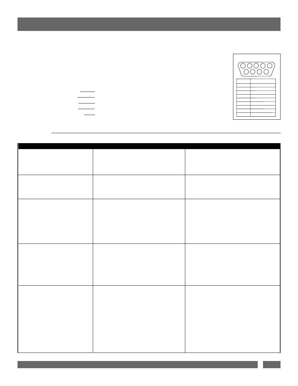
2. PORT SETTINGS
Baud Rate:
9600bps
Data Bits:
8
Start Bits:
1
Stop Bits:
1
Flow Control:
None
Null modem cable not required.
DB9 Pinout Diagram
5 4 3 2 1
6 7 8 9
PIN NO.
1
2
3
4
5
6
7
8
9
SIGNAL
-
RECEIVE DATA
TRNSMIT DATA
-
GROUND
-
-
-
-
COMMANDS
The following are commands that can be made to the M7500-PRO.
- Lan/UTP 5E Module BANKS WIRING MB1000 MB1500 Rackmount UPS, Voltage Regulator & Power Conditioner 2-Outlet Direct Plug-In Surge Protector with Tel/LAN Connectors 2-Outlet Direct Plug-In Surge Protector (End-to-End) 2-Outlet Direct Plug-In Surge Protector with Coaxial In/Out MAX 5400-EX Max 5400 Power Line Management with Voltage Regulation (2 RU, 11 Outlets) MR4000 Power Management System MAX M5300-EX