Patton electronic 1185 User Manual
Page 6
4.0 INSTALLATION
Once the Model 1184 or 1185 is properly configured, it is ready to
connect to the fiber interface, to the serial port, and to the power
source. This section tells you how to make these connections.
4.1 CONNECTION TO THE FIBER INTERFACE
The Model 1184 supports communication between two terminal
equipment at distances to 3 miles (4.8km) and data rates to 128 kbps
(sync) or 19.4 kbps (async). Model 1185 also supports distances up
to 3 miles (4.8km), but at rates up to 256 kbps (sync) or 38.4 (async).
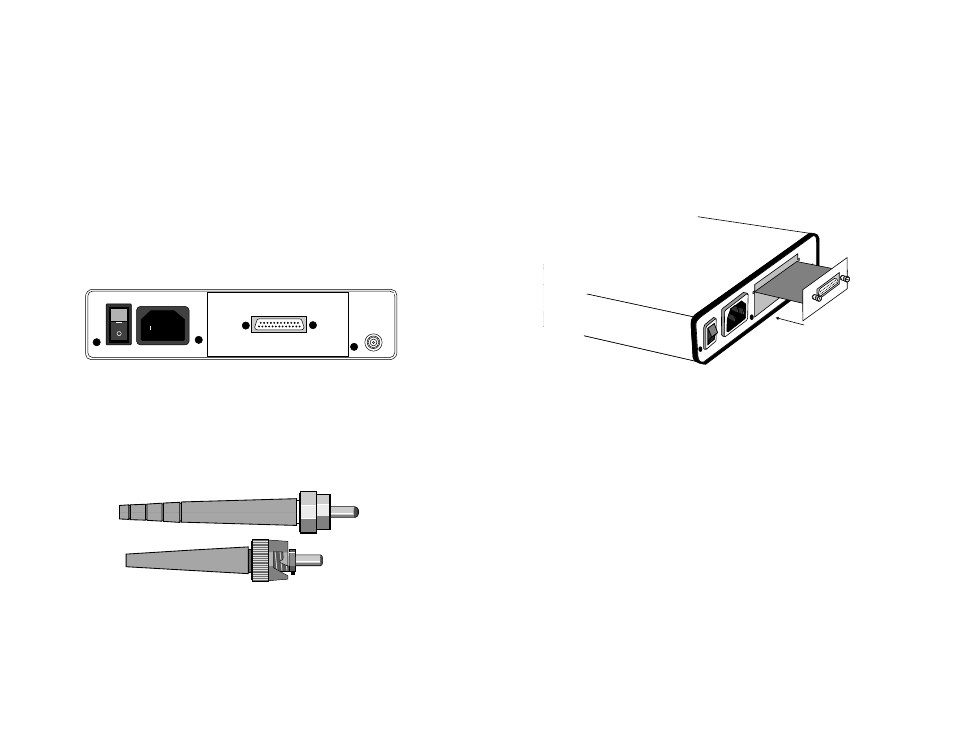
Figure 3 shows the position of the interface connectors on the Model
1184 or 1185 back panel.
These short range modems are designed to work in pairs. You will
need one at each end of single 50 or 62.5 micron multi-mode fiber
cable. The fiber cable connects to each Model 1184 or 1185 using
either an ST or an SMA connector. Figure 4 below shows a close-up of
both connector types.
9
4.2 CONNECTION TO THE SERIAL PORT
The serial port interface on the Model 1184 and 1185 uses
interchangeable QuickConnect™ Modules. Each QuickConnect™
Module has a 50-pin card edge connector on one side and a serial port
interface on the other. Figure 2 below shows how a QuickConnect™
Module plugs into the back of the Model 1184/1185.
4.2.1 Changing QuickConnect™ Modules
When you purchase a particular version of the Model 1184 or
1185, it should be shipped to you with the appropriate QuickConnect™
Module already installed. If you need to install a different
QuickConnect™ Module, follow these steps:
Removing the Existing QuickConnect™ Module
1) Turn the power switch off. Leave the power cord plugged into a
grounded outlet to keep the unit grounded.
2) Loosen the two thumbscrews on the module by turning them
counterclockwise.
3) Grasp the two thumbscrews and gently pull the module from
the unit. Apply equal force to the thumbscrews to keep the
module straight during the removal process.
10
0 OFF
1 ON
Line
Interface Port
Figure 5. Installation of Model 1184/1185 Plug-in Serial Interface Module
ST
SMA
Figure 4.
Close-up of ST and SMA Connectors
Figure 3. Rear Panel of Model 1184/1185, Showing Interface and Power Connectors
Line
1 On
0 Off
Interface Port
Quik-Connect
Interface Module
Fiber