Philips TW0200 User Manual
Page 31
182
. Check of BER with IF Loop: -
oop IF Trans to If Receive and test 140 Mb/ STM-1 on DTA set for 0 PPM and ± 15
PPM. The result should be 0.00 E
-11
5. a) Trans Branching Filter loss: -
The difference between Trans Power at PA out and antenna port will be a Trans
Branching Filter loss.
b) Receive Filter loss: -
Feed RF Frequency at a nominal level to antenna port and measure at Rx in,
Calculate receive filter loss.
Limit: - Tx + Rx combined filter loss should be 6 dB max.
6. Isolation between Transmitter and Receiver:-
- TX – Rx
- Keep Transmitter ON, for Tx – Rx isolation.
- Tune the transmitter frequency at RRF in point on spectrum analyzer.
- Limit: Better than 70 dB
- Rx-Tx
- Feed Rx RF at antenna port and measure at co-axial cable connected to PA out ,
- Limit: Better than 70 dB
7. Waveguide pressurization in Kg/ Cm
2
- Note down Waveguide pressure in Kg/ Cm
2
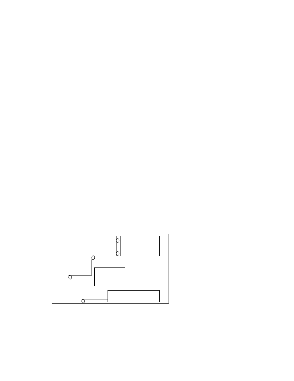
8. Some test of 7 GHz system: - ALC Test (Automatic level control)
- Make the test set up as below Fig. 7-14
- feed -3 dBm to IF in
- Adjust +30 dBm at PA out
- Vary IF level from -1 to -7 dBm
- Observe level at PA out which should be near about constant , one example,
- IF PA
-1 +30.000
-3 +30.05
-5 +29.99
-7 +30.05
Fig. 7-14
Low Transpower alarm:-
- Same set up ALC and go IF level low to see Transpower alarm LED to glow
by 3 dB minimum
- This alarm on display shows at > 33 dBm and < 25 dBm Transpower
- Go low by 1 dB step to get this alarm.
4
L
System
analyzer
IF O/P Level
is varied
IF O/P
70 MHz
Power meter
RF out at Eqpt. top
182