Connecting the audio and video outputs continued, Connecting a second entertainment zone, What you may need – Parasound Halo C1 Controller User Manual
Page 50: 1 composite video cable, 2 unbalanced analog audio interconnects, 1 zone amplifier and pair of speakers, 1 in-wall infrared sensor, 1 ir repeater module, Rca plug 3.5 mm mini plug, Composite video zone outputs
Although the “No OSD” jacks do not pass on-screen display information generated by the C 1,
they will pass status information coming from such source components as VCR and DVD play-
ers, because that information is part of the video signal fed to the C 1.
(Note: No on-screen display is sent to the component video outputs, because on-screen display
circuits reduce video bandwidth and detract from component video’s increased signal purity and
picture clarity. However, OSD is available for composite and S-Video because its effect on these
narrower-bandwidth signals isn’t as noticeable.)
The diagram shows cables to only three of the five component video jacks provided (the ones
marked “Pr,” “Y” and “Pb”), as most home-theater video devices use only those connections.
Professional video gear, computers and a few DVD players and other devices use VGA or RGB
connections that require five cables (for red, green, blue, and horizontal and vertical sync). For
the best possible picture quality, especially for HDTV, we recommend using cables with twist-
on BNC connectors; however, adapters are provided for the more commonly available RCA-plug
cables. (Note: The component video jacks on the C 1, and the plug adapters supplied, are not
color-coded; however, a key to the appropriate cable colors is printed below the bottom row of
component video jacks; from left to right, they are “Red,” “Green,” and “Blue”.)
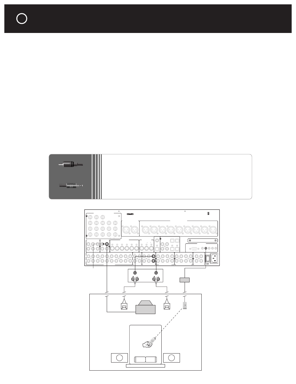
Connecting a Second Entertainment Zone
Optical 1
Optical 3
Coax 1
Coax 2
Coax 3
Coax 4
Optical 2
Optical 4
Video 1
Video 2
Video 3
Video 4
Video 5
Video 6
Audio 1
Audio 2
Audio 3
Audio 4
Balanced Analog Audio Outputs
Balanced Analog Audio Inputs
C2 Controller
Parasound Products, Inc.
San Francisco, California, USA
Input 1
Input 2
Input 3
Output
Component Video Inputs and Outputs
Sync
Red
Green
Blue
H
V
Pr
Y
Pb
Composite Video Inputs
Video Outputs
S-Video Inputs
Video 1
Video 2
Video 3
Video 4
Video 5
Video 6
S-Video Outputs
Record
Main
Digital Out
Coax
Digital Audio Inputs
Optical
Made In
Finland
Expansion Port For
Future Technologies
IR Inputs
– 12V Triggers –
RS-232 Control
External Control
L
R
L
R
Analog Audio Inputs
Tape Monitor
Analog Audio Outputs
Programmable Out
Main Analog Audio Outputs
7.1 Analog Audio Inputs
1
0
AC Power
CAUTION
TO PREVENT ELECTRIC SHOCK,
DO NOT REMOVE COVER. NO USER
SERVICEABLE PARTS INSIDE,
REFER SERVICING TO QUALIFIED
SERVICE PERSONNEL.
Left
Right
Left
Right
Center
Subwoofer
Left Surround
Right Surround
Left Back
Right Back
Pro 1
Video 1
Video 2
Video 3
Video 4
Video 5
Video 6
Pro 3
Pro 1
Pro 4
Pro 2
Sub
Front
Surround
Center
Back
Front
Surround
Center
Sub
Back
Digital Out
Optical
P1
P2
On-Off
Record
OSD
Zone
NoOSD
Main
Main
Zone
Record 1 Record 2
Zone
Audio 5
Play/In
Rec/Out
Composite Video
Zone Outputs
LEFT
SPEAKER
RIGHT
SPEAKER
IR WALL
SENSOR
IR REPEATOR
MODULE
TV
Inputs
Outputs
2 CHANNEL
ZONE AMPLIFIER
REMOTE ZONE
RCA Plug
3.5 mm mini plug
CONNECTING THE AUDIO AND VIDEO OUTPUTS continued
50
What You May Need:
•
1 composite video cable
•
2 unbalanced analog audio interconnects
•
1 zone amplifier and pair of speakers
•
1 in-wall infrared sensor
•
1 IR repeater module