What you may need, One s-video cable with multi-pin plugs – Parasound Halo C1 Controller User Manual
Page 39
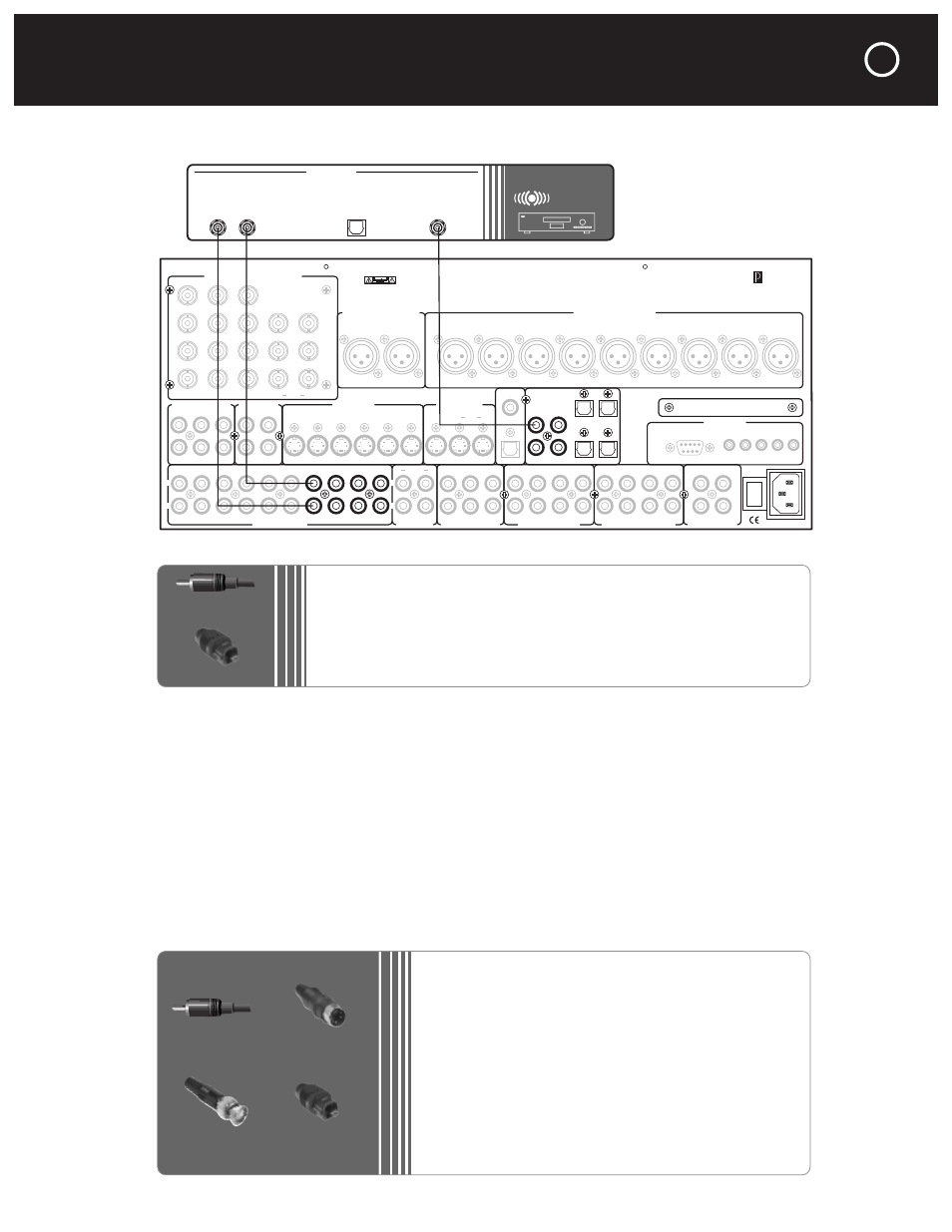
Connecting a CD or Other Audio Source Component to the C 1
For the best possible sound, always use your source component’s digital output, if it has one. It is
not necessary to use the source’s analog outputs as well, unless you plan to record from this source
onto an analog recorder such as a cassette deck or to listen to this source in a remote listening zone.
(Digital signals appear at the main analog outputs but not the analog recording or Zone outputs.)
For FM/AM tuners and similar analog audio gear that lacks digital outputs, only the analog input
connections are used.
Note that the first six analog audio inputs, at the lower left corner (numbered Video 1 through Video
6), are associated with the composite video and S-Video inputs whose numbers they share. For
audio-only sources, it’s best to use inputs Audio 1 through Audio 4, as those inputs cannot be used
with composite or S-Video sources (they can, however be used with component-video sources).
Connecting a DVD Or Other Video Source Component to the C 1
RCA Plug
S-Video Connector
BNC Connector
Toslink Connector
RCA Plug
Toslink Connector
Balanced Analog Audio Outputs
Balanced Analog Audio Inputs
C2 Controller
Parasound Products, Inc.
San Francisco, California, USA
Input 1
Input 2
Input 3
Output
Component Video Inputs and Outputs
Sync
Red
Green
Blue
H
V
Pr
Y
Pb
Composite Video Inputs
Video Outputs
S-Video Inputs
Video 1
Video 2
Video 3
Video 4
Video 5
Video 6
S-Video Outputs
Record
Main
Digital Out
Coax
Digital Audio Inputs
Optical
Optical 2
Optical 1
Optical 4
Optical 3
Coax 1
Coax 2
Coax 3
Coax 4
Made In
Finland
Expansion Port For
Future Technologies
IR Inputs
– 12V Triggers –
RS-232 Control
External Control
L
R
L
R
Audio 1
Audio 2
Audio 3
Audio 4
Analog Audio Inputs
Tape Monitor
Analog Audio Outputs
Programmable Out
Main Analog Audio Outputs
7.1 Analog Audio Inputs
1
0
AC Power
CAUTION
TO PREVENT ELECTRIC SHOCK,
DO NOT REMOVE COVER. NO USER
SERVICEABLE PARTS INSIDE,
REFER SERVICING TO QUALIFIED
SERVICE PERSONNEL.
Left
Right
Left
Right
Center
Subwoofer
Left Surround
Right Surround
Left Back
Right Back
Pro 1
Video 1
Video 2
Video 3
Video 4
Video 5
Video 6
Record
OSD
Zone
NoOSD
Main
Record 1 Record 2
Zone
Audio 5
Play/In
Rec/Out
Pro 3
Pro 1
Pro 4
Pro 2
Sub
Front
Surround
Center
Back
Front
Surround
Center
Sub
Back
Video 1
Video 2
Video 3
Video 4
Video 5
Video 6
Digital Out
Optical
Main
Zone
P1
P2
On-Off
R
L
CD PLAYER
OUTPUTS
Digital Optical
Output
Digital Coaxial
Output
Unbalanced
Analog Audio
CONNECTING AUDIO AND VIDEO SOURCES AND RECORDERS
continued
39
What You May Need:
•
One pair of unbalanced interconnects with RCA plugs
•
One 75-ohm digital coaxial cable with RCA plugs
(OR one optical digital cable with Toslink connectors)
•
CD player with digital and unbalanced analog outputs
What You May Need:
•
One pair of unbalanced interconnects with RCA plugs
•
One 75-ohm digital coaxial cable with RCA plugs (or:
one optical digital cable with Toslink connectors)
•
One S-video cable with multi-pin plugs
•
One composite video cable with RCA plugs (optional)
•
One three-cable component video cable set, with RCA
plugs at one end, RCA or BNC plugs at the other (optional)
•
DVD player with digital and analog audio outputs, plus com-
posite, S-video, and possibly component video outputs