Warning – PB Heat Gas Boiler User Manual
Page 20
18
3. To check the gas supply pressure on the gas valve:
a. Turn off the power at the service switch.
b. Turn off the gas shutoff valve.
c. Using a flat screwdriver, turn the screw inside the
inlet pressure tap fitting (see figure 4.4 and 4.5)
one turn counterclockwise.
d. Attach the manometer tube to the pressure tap
fitting.
e. Open the gas shutoff valve and start the boiler.
f.
Read and record the gas pressure while the boiler
is firing.
g. Turn off the boiler and gas shutoff valve
h. Remove the manometer tube from the pressure
tap fitting and turn the screw to close the internal
valve.
i.
Turn on the gas shutoff valve and boiler service
switch.
4. All gas piping must be leak tested prior to placing the
boiler in operation.
a. If the leak test pressure requirement is higher
than the maximum inlet pressure noted in Table
4.4, the boiler must be isolated from the gas
supply piping system.
b. If the gas valve is exposed to pressures exceeding
13.5" of water, the gas valve must be replaced.
5. Install the boiler such that the gas ignition system
components are protected from water (dripping,
spraying, rain, etc) during operation and service
(circulator replacement, condensate trap cleanout,
and control replacement, etc).
E. MAIN GAS VALVE - OPERATION
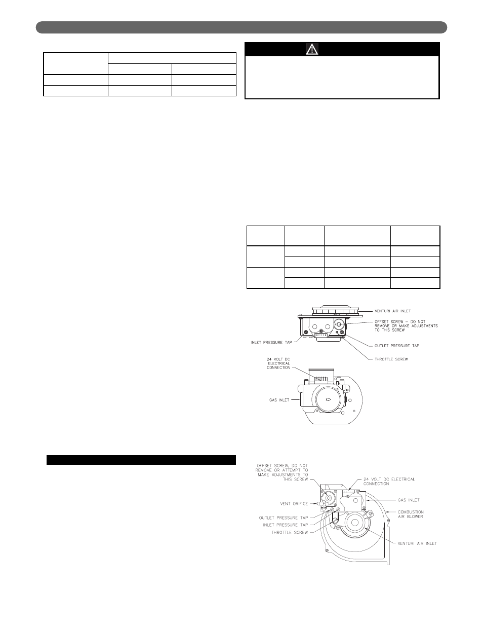
1. Figure 4.4 shows an illustration of the gas valve/venturi
assembly for the Pinnacle PI-T50 and PI-T80 and
Figure 4.5 shows an illustration of the gas valve/venturi
assembly for the PI-80, PI-140, and PI-199.
a. The throttle screw on either of these valves
should not be adjusted without a means to
measure carbon monoxide (CO) and carbon
dioxide (CO²) emissions.
b. For both gas valve arrangements, turning the
throttle screw clockwise will decrease the gas flow
(decreasing CO²) and turning it counterclockwise
will increase the gas flow (increasing CO²).
c. The recommended CO² settings are given in
Table 4.5. In no case should the boiler be
allowed to operate with CO emissions in excess
of 150 ppm.
2. Refer to Section 5, Venting for information on
obtaining vent samples from this boiler.
GAS PIPING
Do not adjust the throttle screw without monitoring
the carbon dioxide (CO²) and carbon monoxide (CO)
in the vent pipe. Vent CO emissions above 400 ppm
are in excess of most safety standards.
WARNING
Gas
Type
Pressure (inches of water)
Minimum
Maximum
Natural
3.7
13.5
LP
3.7
13.5
Table 4.4: Maximum and Minimum Fuel Pressure
Gas Type
Firing
Rate
Vent CO²
Vent CO
Natural
Low
8-1/2% to 9-1/2%
< 50 ppm
High
8-1/2% to 9-1/2%
< 100 ppm
LP
Low
9-1/2% to 10-1/2%
< 50 ppm
High
9-1/2% to 10-1/2%
< 100 ppm
Table 4.5: Recommended Vent CO² Settings
Figure 4.4: Gas Valve/Venturi PI-T50/PI-T80
Figure 4.5: Gas Valve/Venturi PI-80, PI-140, PI-199