Logic circuitry, Ic card interface tda8002c – Philips TDA8002C User Manual
Page 11
1999 Oct 12
11
Philips Semiconductors
Product specification
IC card interface
TDA8002C
Logic circuitry
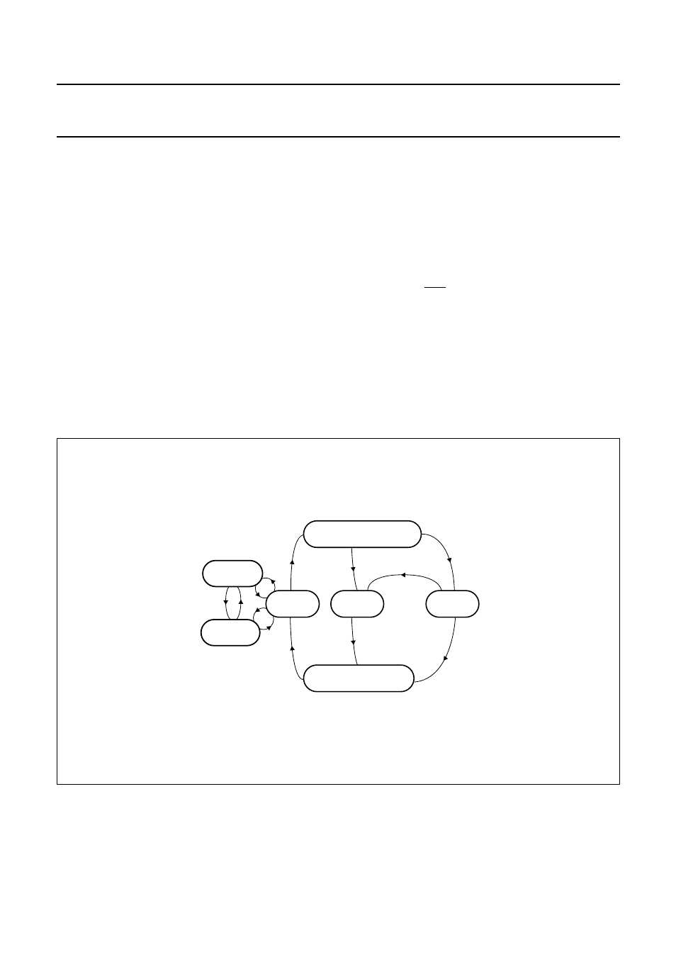
After power-up, the circuit has six possible states of
operation. Figure 9 shows the state diagram.
I
DLE MODE
After reset, the circuit enters the idle mode. A minimum
number of functions in the circuit are active while waiting
for the microcontroller to start a session:
•
All card contacts are inactive
•
I/OUC, AUX1UC and AUX2UC are high-impedance
•
Oscillator (XTAL) runs, delivering CLKOUT
•
Voltage supervisor is active.
L
OW
-
POWER MODE
When pin MODE goes LOW, the circuit enters the
low-power (sleep) mode. As long as pin MODE is LOW no
activation is possible.
If pin MODE goes LOW in the active mode, a normal
deactivation sequence is performed before entering the
low-power mode. When pin MODE goes HIGH, the circuit
enters the normal operating mode after a delay of at least
6 ms (96 cycles of CLKOUT). During this time the
CLKOUT remains at 16 kHz.
•
All card contacts are inactive
•
Oscillator (XTAL) does not operate
•
The V
DD
supervisor, ALARM output, card presence
detection and OFF output remain functional
•
Internal oscillator is slowed to 32 kHz, providing 16 kHz
on CLKOUT.
A
CTIVE MODE
When the activation sequence is completed, the
TDA8002C will be in the active mode. Data is exchanged
between the card and the microcontroller via the I/O lines.
Fig.9 State diagram.
handbook, full pagewidth
MGE735
POWER
OFF
ACTIVE
MODE
LOW-POWER
MODE
IDLE
MODE
FAULT
ACTIVATION
DEACTIVATION