Patton electronic 1008 User Manual
Page 14
3.0 CONFIGURATION
The Model 1008 is configured using two PC board mounted
4-position DIP switches. This section shows how to access the DIP
switches, provides an overview of the factory default settings, and
describes all possible configuration options. For instructions on how to
configure the Model 1008 for specific applications, refer to Section 5.0.
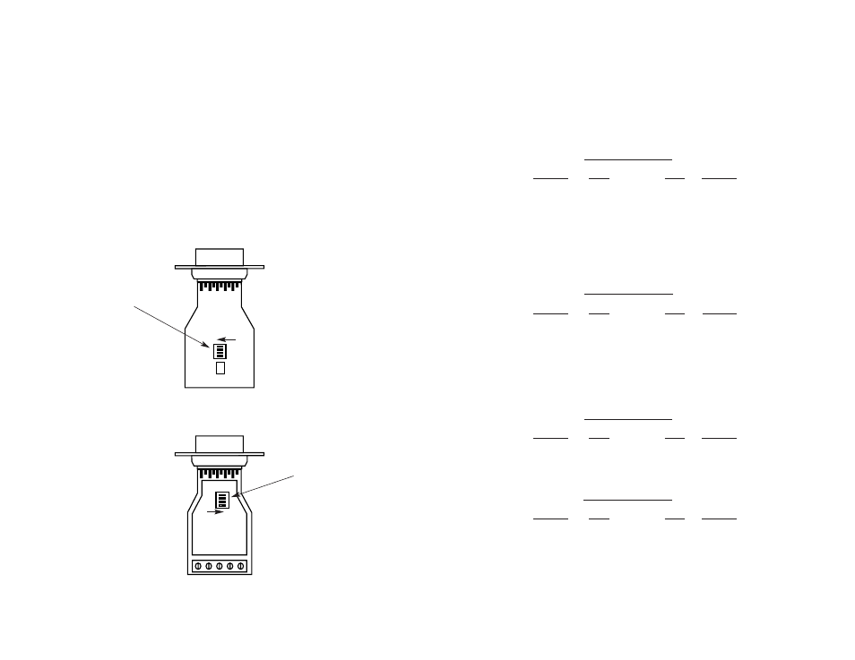
3.1 ACCESSING THE DIP SWITCHES
The Model 1008 has main PC board and a daughter board. DIP
switch S1 is located on the underside of the main PC board (see Figure
1, below). DIP switch S2 is located on the top of the daughter board
(see Figure 2, below).
4
(Continued)
When connecting two Model 1008s, it is necessary to use a
crossover cable. The diagrams below show how a crossover cable
should be constructed for the following environments: 4-wire RJ-11,
4-wire RJ-45, 2-wire RJ-11 or 2-wire RJ-45.
RJ-11 Cable (4-Wire)
SIGNAL
PIN#
PIN#
SIGNAL
GND
†
1-----------------------6
GND
†
RCV-
2-----------------------4
XMT-
XMT+
3-----------------------5
RCV+
XMT-
4-----------------------2
RCV-
RCV+
5-----------------------3
XMT+
GND
†
6-----------------------1
GND
†
†
Connection to ground is optional
RJ-45 Cable (4-Wire)
SIGNAL
PIN#
PIN#
SIGNAL
GND
†
2-----------------------7
GND
†
RCV-
3-----------------------5
XMT-
XMT+
4-----------------------6
RCV+
XMT-
5-----------------------3
RCV-
RCV+
6-----------------------4
XMT+
GND
†
7-----------------------2
GND
†
RJ-11 Cable (2-Wire)
SIGNAL
PIN#
PIN#
SIGNAL
XMT+
3-----------------------3
XMT+
XMT-
4-----------------------4
XMT-
RJ-45 Cable (2-Wire)
SIGNAL
PIN#
PIN#
SIGNAL
XMT+
4-----------------------4
XMT+
XMT-
5-----------------------5
XMT-
†
Connection to ground is optional
13
ON
1234
Switch S1
Figure 1. Underside of Model 1008 main PC board, showing the location of DIP switch S1.
ON
1234
Switch S2
Figure 2. Top of Model 1008 daughter board, showing the location of DIP switch S2.
ON
1234
ON
ON