Patton electronic 1008 User Manual
Page 11
3.1.3 DIP SWITCH S2 SETTINGS
DIP switch S2 is used to configure carrier control, RTS/CTS delay
and communication protocol. The summary table below shows the
factory default settings for switch S2. Following the summary table is a
detailed description of each individual switch.
*Note: Switches S2-3 and S2-4 should be switched simultaneously
S2-1: Carrier Control Method
The setting for switch S2-1 determines whether the carrier is
“Constantly On” or “Controlled by RTS”. This setting allows for
operation in switched carrier, multipoint and/or hardware handshaking
applications.
S2-1
Setting
On
Controlled by RTS
Off
Constantly ON
S2-2: RTS/CTS Delay
The setting for switch S2-2 determines the amount of delay
between the time the Model 1008 “sees” RTS and when it sends CTS.
Note: RTS/CTS Delay setting should be based upon transmission
timing.
S2-2
Setting
On
8 mSec
Off
no delay
S2-3 and S2-4: “Transmit Off” Impedance
Switches S2-3 and S2-4 are set together to determine whether the
receiving device “sees” the impedance of the Model 1008’s transmitter
as being “high” or “intermediate” when the transmitter is turned off. The
“intermediate” setting is useful in half-duplex environments where the
receiving device does not respond well to the “high” setting.
S2-3
S2-4
Setting
On
On
Intermediate Impedance
Off
Off
High Impedance
7
SWITCH S2 SUMMARY TABLE (factory defaults in bold)
Position
Function
ON Position
OFF Position
S2-1
Carrier Control
RTS
Constantly ON
S2-2
RTS/CTS Delay
8 mSec
No Delay
S2-3*
“XMT Off” impedance
Intermediate
High
S2-4*
“XMT Off” impedance
Intermediate
High
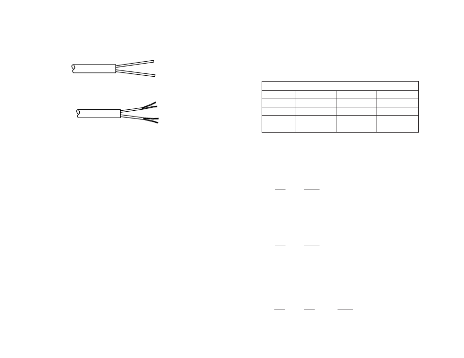
2. Strip the outer insulation from the twisted pair(s) about one inch
from the end.
3. Strip the insulation on each of the twisted pair wires about .25”.
4. In a two pair circuit, connect
one pair of wires to XMT+ and
XMT- (transmit positive and negative) on the terminal block, making
careful note of which color is positive and which color is negative.
5. Connect the
other pair of wires to RCV+ and RCV- (receive
positive and negative) on the terminal block, again making careful note
of which color is positive and which color is negative.
Ultimately, you will want to construct a two pair crossover cable that
makes a connection with the two Model 1008s as shown below.
6. In a single pair circuit, use
only the transmit (XMT) pair as
shown below:
Note: If there is a shield around the telephone cable, it may be
connected to “G” on the terminal block. To avoid ground loops, we
recommend connecting the shield at the computer end only. A ground
wire is
not necessary for proper operation of the Model 1008.
(Continued)
10
XMT+--------------------------------------------------XMT+
XMT----------------------------------------------------XMT-