Patton electronic 1070RC User Manual
Page 19
5.2 POWER-UP
There is no power switch on the Model 1070RC: Power is
automatically applied to the 1070RC when its card-edge connector
makes contact with the chassis' mid-plane socket, or when the chassis'
power supply is turned on.
Note: The 1070RC is a "hot swappable"
card--it will not be damaged by plugging it in or removing it while the
rack is powered up.
When the local and remote Model 1070RCs are
both powered up, and
are passing data
normally, the following LED conditions will exist:
• PWR = green
• TD & RD = flashing red and green
• Control In & Control Out = green
• TEST = off
18
17
5.3 TEST MODES
The Model 1070RC offers two diagnostic modes: local analog loop
and remote analog loop. These test modes are activated
simultaneously by depressing the "Test" button on the front panel of the
Model 1070RC.
Local Analog Loop
The Local Analog Loop test mode causes any data sent to the
local 1070RC by the local RS-232 device to be echoed
back to that RS-
232 device. For example, characters typed on the keyboard of a
terminal will appear on the terminal screen. If characters are not
echoed back, check the connection between the local RS-232 device
and the local 1070RC. All 1070RC's in the system should be tested in
this manner
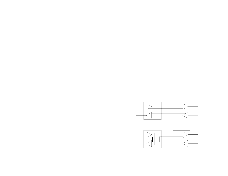
Remote Analog Loop
The Remote Analog Loop test mode causes any characters sent
from the
remote 1070RC to the local 1070RC to be returned back to the
remote device (see Figure 13). Note: Only the local 1070RC should
be in "test" mode. The remote 1070RC should be in "normal"
operating mode or this test will not work. If no characters are echoed
back, check the wiring between the two 1070RCs. Be sure to wire the
units according to the instructions in Section 4.0 Installation.
RD
TD
TD
RD
Local 1070RC
In Normal Mode
Remote 1070RC
In Normal Mode
TX+
TX-
RX-
RX+
RX+
RX-
TX-
TX+
RD
TD
TD
RD
Local 1070RC
In Loopback Mode
Remote 1070RC
In Normal Mode
RX+
RX-
TX-
TX+
TX+
TX-
RX-
RX+
Figure 13. Normal operating mode vs. loopback test mode