Removing the existing fan tray assembly, Warning, Procedure – Paradyne Fan Tray Assembly 8820-S3-900 User Manual
Page 2
2
January
2005
8820-A2-GZ48-00
Removing the Existing Fan Tray Assembly
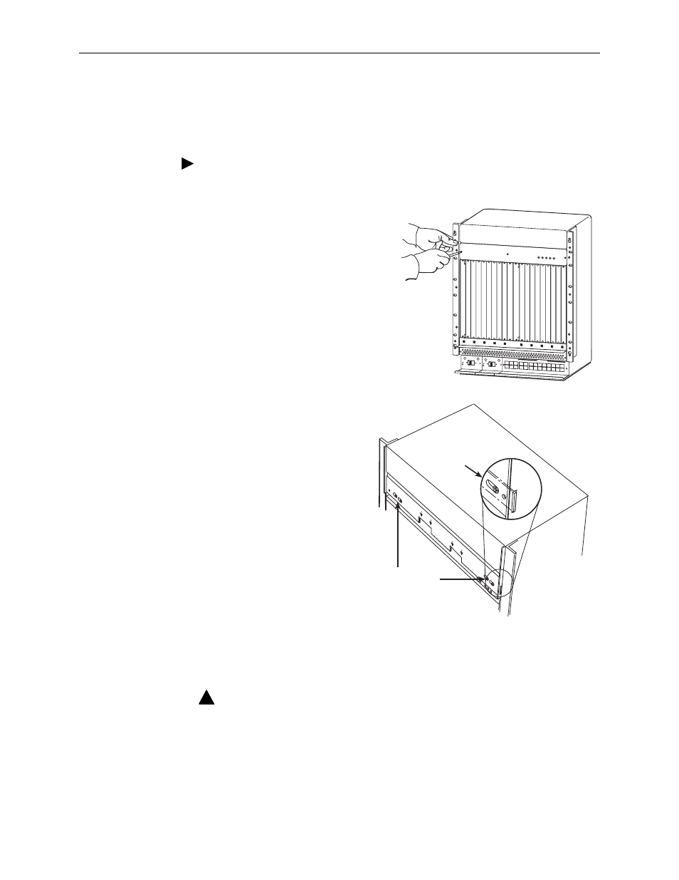
You will need a Phillips screwdriver to remove the vent cover and fan tray.
Procedure
To remove the existing fan tray assembly:
1. Remove three screws from the fan
cover plate, and then remove the
cover plate from the chassis, taking
care not to damage the LED
protruding through the cover plate.
2. Loosen (but do not remove)
the two screws on each
locking bracket, and use
them to slide both locking
brackets toward the middle
of the front panel until the
ends clear the slots in the
side plates.
NOTE:
There are two cutouts in the front face of the fan tray labeled PULL AREA.
This is where you place your fingers to pull the fan tray out of the chassis.
WARNING:
A MECHANICAL HAZARD EXISTS DUE TO ROTATING FAN BLADES. KEEP
HANDS AND FINGERS AWAY FROM FAN BLADES DURING REMOVAL OF
FAN TRAY. USE ONLY THE DESIGNATED PULL AREAS TO DISENGAGE
THE FAN TRAY.
00-16792
ALARMS
Major Minor
Fan
B
A
POWER
SERIAL
SMCM
CLOCK
A
ALARM
2
4
6
8
10
12
14
16
18
1
3
5
7
9
11
13
15
17
LAN/WAN SLOT
B
CLOCK
B
A
SERIAL
MCC
AC
ALARM
48V R
TN
48V NEG
POWER ENTRY MODULE
LEFT UNIT: LINE A
RIGHT UNIT: LINE B
WARNING! POWER MUST BE DISCONNECTED AT THE S
OURCE
BEFORE REMOVING OR INSTALLING THIS PWR ENTRY MODULE
48V R
TN
48V NEG
POWER ENTRY MODULE
LEFT UNIT: LINE A
RIGHT UNIT: LINE B
WARNING! POWER MUST BE DISCONNECTED AT THE S
OURCE
BEFORE REMOVING OR INSTALLING THIS PWR ENTRY MODULE
00-16793
CA
UTION!
DO
N
OT
PL
AC
E FIN
G
ER
S
UN
DE
R
TH
E F
AN
TR
AY
US
E
THE
D
ES
IG
NA
TE
D
PU
LL
AR
EAS
CA
UTION!
DO
N
OT
P
LA
CE
FIN
GE
RS
UN
DE
R T
HE
FA
N T
RA
Y
US
E T
HE
D
ES
IG
NA
TE
D
PU
LL
A
RE
AS
PULL
AREA
PULL
A
REA
Loosen Screws
Locking
Bracket
!