Hardware setup 2-15, Jfp1 pin definition jfp1 (intel spec), Jfp2 pin definition – Premio Computer Premio Computer User Manual
Page 61: Jfp2
Hardware Setup
2-15
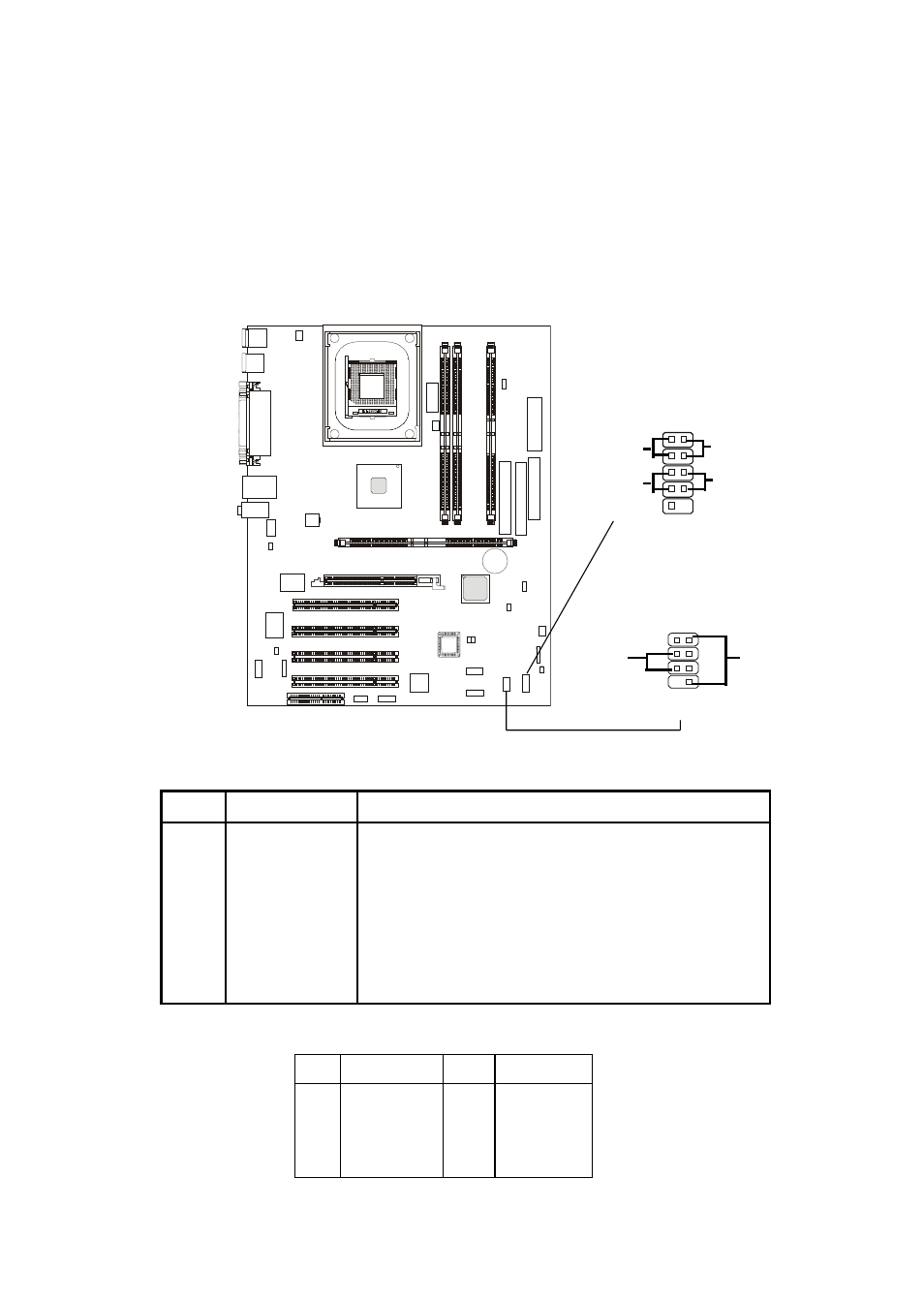
Front Panel Connector: JFP1 and JFP2 (Optional Intel
spec)
This connector is for electrical connection to the front panel switches
and LEDs.
JFP1 Pin Definition
JFP1
(Intel spec)
1 2
HDD
LED
Reset
Switch
Power
LED
Power
Switch
10
9
PIN
SIGNAL
PIN
SIGNAL
1
GND
2
SPK-
3
SLED
4
BUZ+
5
PLED
6
BUZ-
7
NC
8
SPK+
JFP2 Pin Definition
PIN
SIGNAL DESCRIPTION
1
HD_LED_P
Hard disk LED pull-up
2
FP PWR/SLP
MSG LED pull-up
3
HD_LED_N
Hard disk active LED
4
FP PWR/SLP
MSG LED pull-up
5
RST_SW_1
Reset Switch 1
6
PWR_SW_P
Power Switch high reference pull-up
7
RST_SW_2
Reset Switch 2
8
PWR_SW_N
Power Switch low reference pull-down to GND
9
RSVD_DNU
Reserved. Do not use.
JFP2
Speaker
8
7
1 2
Power
LED