Patton electronic 1004ABRC User Manual
Page 11
19
20
5.0 OPERATION
Once you have configured each Model 1004ABRC and connected
the cables, you are ready to operate the units. Section 5.0 describes
the LED status monitors and the power-up procedure.
5.1 LED STATUS MONITORS
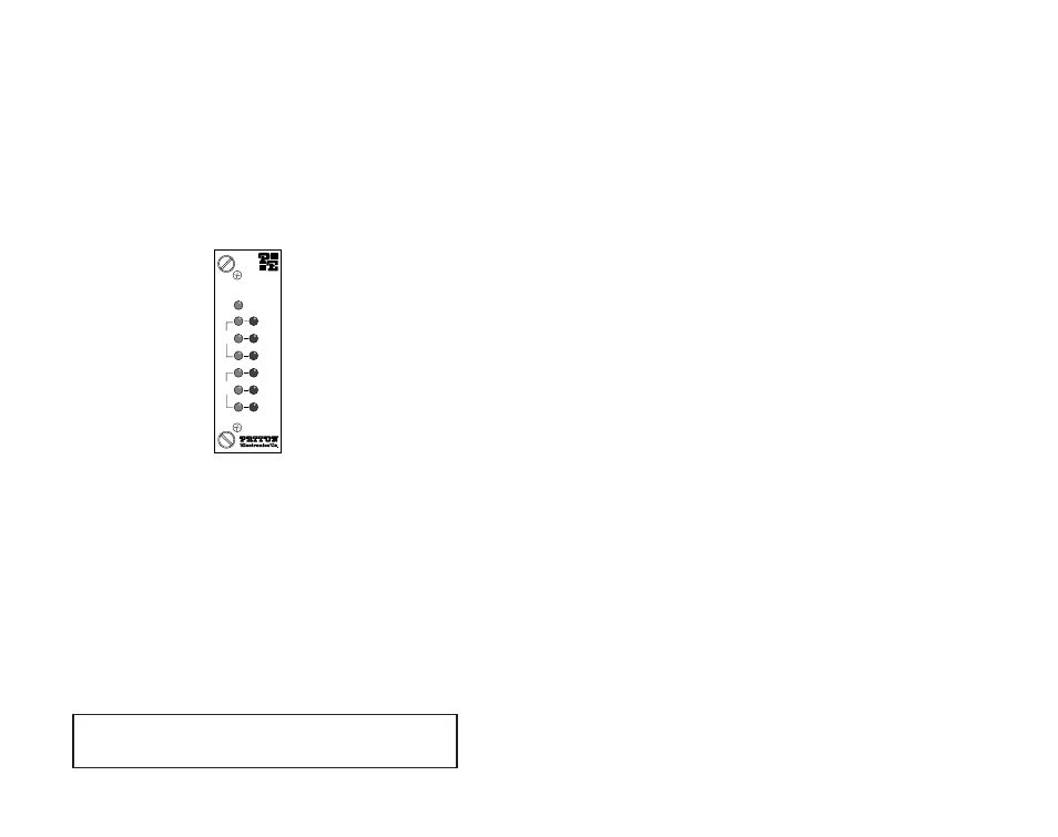
The Model 1004ABRC features front panel LEDs that indicate the
condition of the modem and communication link. Figure 6 (below)
shows the positions of the LEDs.
•
The green “PWR” LED glows when power is applied to
the modem through its mid-plane chassis connection.
•
The green “TD” and “RD” LEDs show positive state data
activity. The red “TD” and “RD” LEDs show negative state
data activity. A solid red light indicates an idle state.
•
The green “CD” LED lights when the receive carrier is
detected; the red LED lights when the receive carrier is
absent.
5.2 POWER-UP
There is no power switch on the Model 1004ABRC: Power is auto-
matically applied to the 1004ABRC when its card-edge connector
touches the chassis’ mid-plane socket, or when the chassis’ power is
turned on.
APPENDIX A
PATTON ELECTRONICS MODEL 1004ABRC
SPECIFICATIONS
Transmission Format:
Asynchronous
Data Rate:
0 to 115.2 Kbps
Surge Protection:
Silicon Avalanche Diodes
Control Signals:
DSR turns “ON” immediately after the termi-
nal raises DTR; DCD turns “ON” after re-
cognizing the receive signal from the line;
CTS turns on after the terminal raises RTS
Transmission Line:
2-wire or 4-wire, unconditioned twisted pair
Transmit Mode:
Full or half duplex
Transmit Level:
2V ± 10% differential output voltage
Carrier:
Controlled by data transitions
RTS/CTS Delay:
8 msec or zero
Echo Mode:
Echo and No Echo, supported in both
2-wire and 4-wire modes
Receiver Impedance:
Low (120 ohms), High (100k Ohms)
Line Connection:
RJ-11 or RJ-45 jack
Surge Protection:
Silicon Avalanche Diodes on twisted pair
interface from each line to frame ground
Power Supply:
Rack-mount power supply is switchable
between 120V and 240V AC; rack chassis
supplies 10V AC to the Model 1004ABRC,
typical consumption is 700 mW per card
Fuse:
400mA for 120V applications; 200mA for
240V applications
Temperature Range:
0-50°C (32-122°F)
Altitude:
0-15,000 feet
Humidity:
Up to 95% non-condensing
Dimensions:
0.95”w x 3.1”h x 5.4”l
Figure 6. The Model 1004ARC front panel, showing LED positions
Model 1004RC
Power
TD
RD
CD
TD
RD
CD
Unit
A
Unit
B
NOTE:
The 1004ABRC is a “hot swappable” card—it will not be
damaged by plugging it in or removing it while the rack is pow-
ered up.