Lower chute (see fig. 8) use hardware - - group "e – Poulan C38D User Manual
Page 9
9
WA
RN
ING
Do
no
t o
pe
rat
e m
ow
er
un
les
s c
on
tai
ne
r is
pro
pe
rly
is
su
bje
ct
to
we
ar
an
d d
eti
eri
ora
tio
n.
Ch
eck
ba
g f
req
ue
ntl
y. R
ep
lac
e w
he
n
cra
cke
d o
r d
am
ag
ed
. U
se
on
ly a
rec
om
me
nd
ed
rep
lac
em
en
t c
on
tai
ne
r.
WA
RN
IN
G
02082
02343
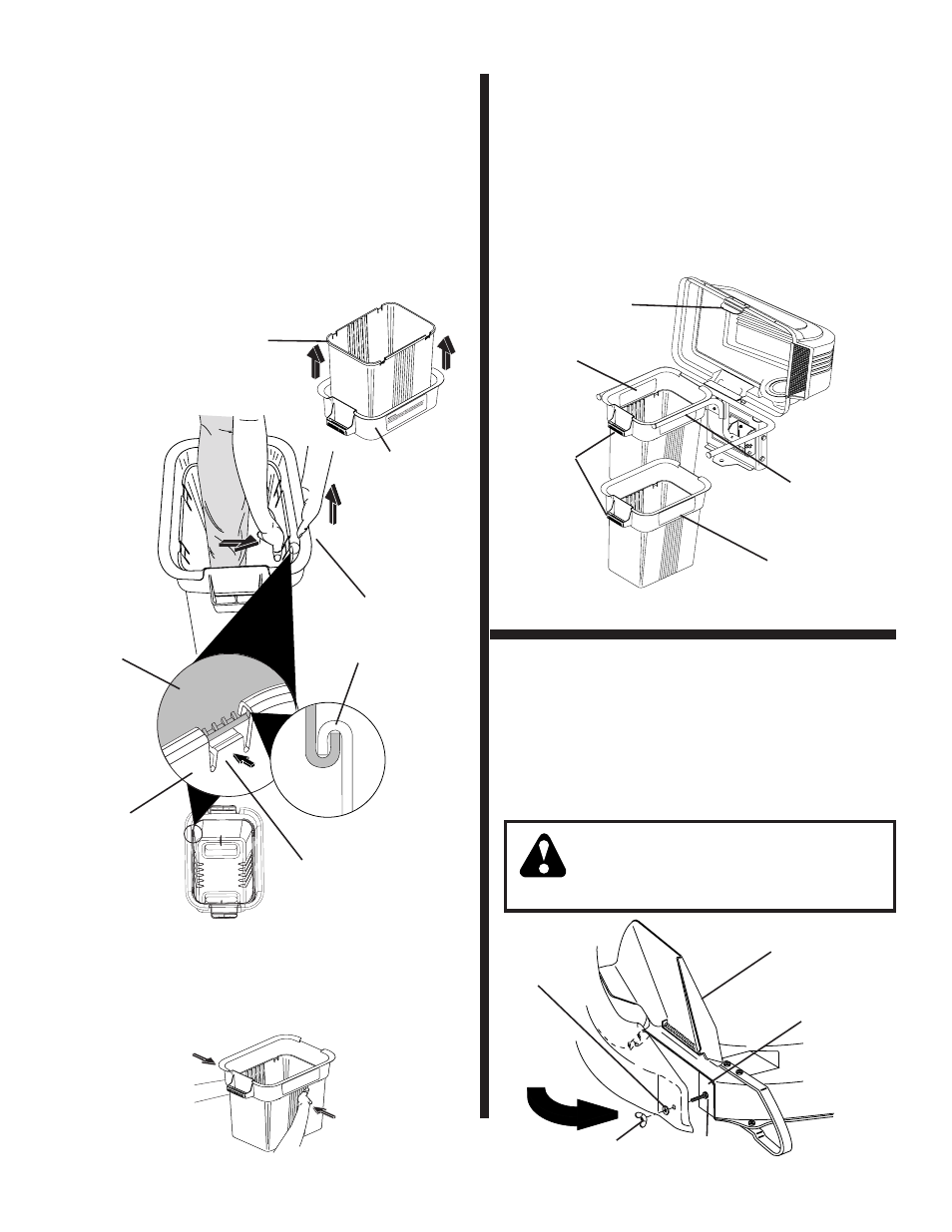
CONTAINER
MOUNTING
(See
Fig.
7)
No hardware required
1. Install one container to left side fi rst with warning to
outside of unit. Install other container to right side.
NOTE: Right con tain er should always over lap left con tain er
at center sup port.
2. Close cover and lock latch handle over center support
tube.
7
COVER LATCH
HANDLE
CENTER
SUPPORT
TUBE
CONTAINER
WARNING
CONTAINER
HANDLE
FIG. 7
CONTAINER
WARNING
DEFLECTOR SHIELD
MOWER DECK
BAFFLE
WASHER
LOWER CHUTE (See Fig. 8)
Use Hardware - - GROUP "E"
1. Raise and hold defl ector shield in upright position.
2. Slide back edge of chute over rear corner of mower
deck and pivot forward.
3. Align slot in lower chute with hex bolt in mower deck
baffl e and close chute over deck openning.
4. Secure with washer and wing nut.
CAUTION: Do not remove discharge
guard from mower. Raise and hold
guard when attaching lower chute
and allow it to rest on chute while in
operation.
WING NUT
HEX BOLT
FIG. 8
8
PRESS TOGETHER
TO FORM SEAL
WHILE LIFTING
TOP HALF
02089
CONTAINER
BOTTOM
HALF
CONTAINER
TOP HALF
ASSEMBLY CHECK: Squeeze sides of lower half of con-
tain er and check that there is no gap between upper and
lower halves. If a gap appears, unlock tabs to separate
container halves and repeat instructions above.
LOCKING
TAB
WA
RNI
NG
Do
no
t o
pe
rat
e mo
we
r u
nle
ss
co
ntai
ner
is
prop
e
rly
iss
ub
jec
t to
we
ar
an
d d
eti
eri
ora
tio
n.
Che
ck
ba
g f
req
u
en
tly.
Re
pla
ce
wh
en
cra
cke
d o
r d
ama
ge
d.
Us
e o
nly
a r
ec
om
me
nd
ed
rep
lac
em
ent
con
tai
ner
.
02097
FIG. 6
02739
CONTAINER
BOTTOM HALF
CONTAINER
TOP HALF
CONTAINER ASSEMBLY (See Fig. 6)
No hardware required
1. Place bottom half inside of top half, as shown.
2. Place one foot inside bottom half and lift top half to
meet bottom half.
3. Press halves tightly together while lifting top to lock
into place as shown.
IMPORTANT: BEFORE LOCKING THE TABS, HOOKED EDGES
ON BOTH HALVES MUST OVERLAP TO FORM SEAL AS SHOWN
IN INSET.
4. Repeat for second container.
6