Assembly and adjustments – Porter-Cable PCB370SS User Manual
Page 12
12
ASSEMBLY AND ADJUSTMENTS
Estimated Assembly Time: 25 - 40 Minutes.
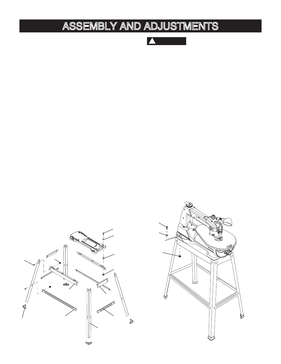
INSTALLING THE STAND (FIG. A)
1. Unpack all parts and group by type and size. Refer
to the parts list for correct quantities.
2.
Bag “H” -
Attach one short upper support (1) to top of
leg (2) using one bolt (3) and nut (4).
NOTE:
● Align detents in stand leg with support brackets to
ensure proper fit.
● Do not tighten bolts until stand is properly
aligned (see step #8 before tightening).
3. Attach other end of short upper support (1) to top of
another leg (2) using one bolt (3) and nut (4).
4.
Bag “H” -
Attach one short bottom support (5) to
center of each leg using bolt (3) and nut (4). This
completes the front frame section.
5. Assemble rear frame section in exactly the same
manner.
6.
Bag “H” -
Join front and rear frame assemblies using
two long upper supports (6) and two long bottom
supports (7), bolts and nuts.
7.
Bag “H” -
Insert foot pad (8) into bottom of leg.
Repeat for each leg.
8. Place stand on level surface and adjust so all legs
are contacting the floor and are at similar angles to
the floor, and detents in stand leg align with support
brackets, then tighten all bolts.
NOTE: To avoid rocking, all bolts must be tightened
securely.
Fig. A
9
10
12
1
5
2
7
6
4
8
3
11
Front Side
Frame Assembly
● The stand is designed only for use with scroll
saw.
● Do not climb, sit or stand on the stand assembly.
● Do not use the stand on uneven or unstable
surface.
● To avoid injury, do not connect this scroll saw to
the power source until it is completely assembled
and adjusted and you have read and understood
this instruction manual.
MOUNTING THE SCROLL SAW (FIG. A, B)
1. To mount your scroll saw to the stand, position the
leg stand on a firm, level surface.
2. Matching the holes (13) in the scroll saw base with
the holes in the leg stand, place the scroll saw on the
stand.
3. Secure the stand and saw using the hex head bolts
(9), flat washers (10), sleeve (11-Fig. A) and nuts (12)
provided.
4. Tighten all four nuts.
NOTE: Do not over tighten nuts holding saw to
stand. This may damage the saw base.
Fig. B
WARNING
!
OFF
9
10
12
13