PMC-Sierra Pm25LV512 User Manual
Page 12
12
Programmable Microelectronics Corp.
Issue Date: February, 2004, Rev: 1.4
PMC
Pm25LV512/010
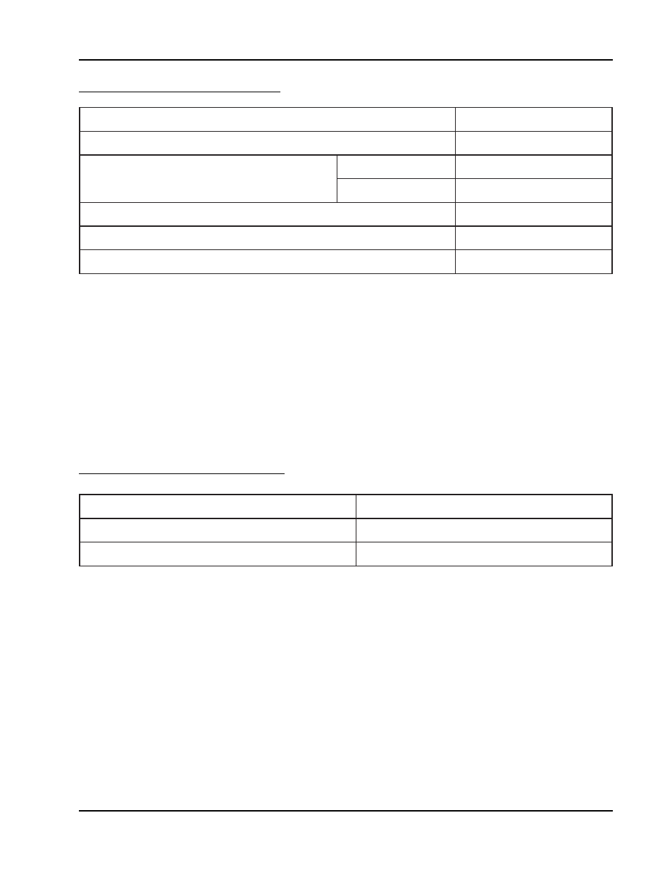
DC AND AC OPERATING RANGE
ABSOLUTE MAXIMUM RATINGS
(1)
Notes:
1. Stresses under those listed in “Absolute Maximum Ratings” may cause permanent damage
to the device. This is a stress rating only. The functional operation of the device or any other
conditions under those indicated in the operational sections of this specification is not
implied. Exposure to absolute maximum rating condition for extended periods may affected
device reliability.
2. Maximum DC voltage on input or I/O pins are V
CC
+ 0.5 V. During voltage transitioning
period, input or I/O pins may overshoot to V
CC
+ 2.0 V for a period of time up to 20 ns.
Minimum DC voltage on input or I/O pins are -0.5 V. During voltage transitioning period,
input or I/O pins may undershoot GND to -2.0 V for a period of time up to 20 ns.
s
a
i
B
r
e
d
n
U
e
r
u
t
a
r
e
p
m
e
T
5
6
-
o
5
2
1
+
o
t
C
o
C
e
r
u
t
a
r
e
p
m
e
T
e
g
a
r
o
t
S
5
6
-
o
5
2
1
+
o
t
C
o
C
e
r
u
t
a
r
e
p
m
e
T
g
n
i
r
e
d
l
o
S
d
a
e
L
t
n
u
o
M
e
c
a
f
r
u
S
e
g
a
k
c
a
P
d
r
a
d
n
a
t
S
0
4
2
o
s
d
n
o
c
e
S
3
C
e
g
a
k
c
a
P
e
e
r
f
-
d
a
e
L
0
6
2
o
s
d
n
o
c
e
S
3
C
s
n
i
P
ll
A
n
o
d
n
u
o
r
G
o
t
t
c
e
p
s
e
R
h
t
i
w
e
g
a
t
l
o
V
t
u
p
n
I
)
2
(
V
o
t
V
5
.
0
-
C
C
V
5
.
0
+
d
n
u
o
r
G
o
t
t
c
e
p
s
e
R
h
t
i
w
e
g
a
t
l
o
V
t
u
p
t
u
O
ll
A
V
o
t
V
5
.
0
-
C
C
V
5
.
0
+
V
C
C
)
2
(
V
0
.
6
+
o
t
V
5
.
0
-
r
e
b
m
u
N
t
r
a
P
0
1
0
/
2
1
5
V
L
5
2
m
P
e
r
u
t
a
r
e
p
m
e
T
g
n
i
t
a
r
e
p
O
0
o
5
8
o
t
C
o
C
y
l
p
p
u
S
r
e
w
o
P
c
c
V
V
6
.
3
-
V
7
.
2