English – Polk Audio PA400.1 User Manual
Page 5
W W W . P O L K A U D I O . C O M / A M P S
9
8
P A
1 2 V
A M P L I F I E R S
ENGLISH
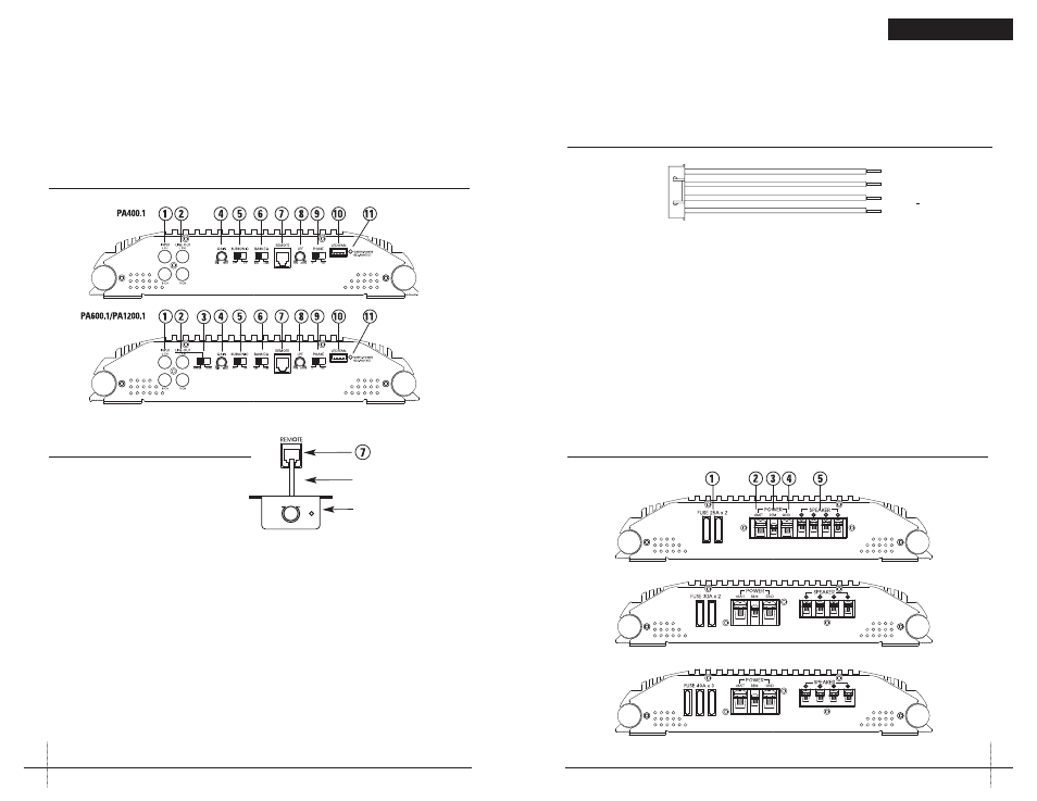
REAR PANEL CONNECTIONS
1. Fuses—These fuses protect the amplifier against
internal electrical damage and are meant to protect
the amplifier only. All other power connections should
be fused at the source. The PA400.1 uses 2-25A fuses,
the PA600.1 uses 2-30A fuses and the PA1200.1 uses
3-40A fuses.
2. (+) 12 Volt Power—Connect this terminal through a
FUSE or CIRCUIT BREAKER to the positive terminal of
the vehicle battery or the positive terminal of an isolated
audio system battery.
WARNING: Always protect this power wire by installing
a fuse or circuit breaker of the appropriate size within
12 inches of the battery terminal connection.
3. Remote Turn On—This terminal turns on the amplifier
when (+) 12 volt is applied to it. Connect it to the remote
turn on lead of the head unit or signal source.
4. Ground—Connect this terminal directly to the sheet
metal chassis of the vehicle, using the shortest wire
necessary to make this connection. Always use wire of
the same gauge or larger than the (+) 12 volt power wire.
The chassis connection point should be scraped free of
paint and dirt. Use only quality crimped and/or soldered
connectors at both ends of this wire. DO NOT connect
this terminal directly to the vehicle battery ground
terminal or any other factory ground points.
5. Speaker Terminals—Connect subwoofers to these
terminals. (Refer to the Speaker Wiring Diagrams
section of this guide.)
FIGURE 3—AMPLIFIER CONNECTIONS—REAR (PA400.1/PA600.1/PA1200.1)
PA400.1
PA600.1
PA1200.1
FIGURE 2—LED/FAN HARNESS
BLACK
BLUE
BLACK
RED
_
+
_
+
TO LEDs
TO FAN
FRONT PANEL CONNECTIONS/CONTROLS
1. RCA Input Jacks—Accepts line level outputs from
head units or signal processors at voltages between
150mV and 7.5 volts.
2. RCA Line Output Jacks—These pass through
RCA jacks can be used to send the input signal to
a second amplifier.
3. Slave/Master Switch—Controls whether the
amplifier is a slave or master when connected in
combined amplifier configurations. (Refer to the
Combined Amplifiers section of this guide.)
4. Gain Control—Controls the amplifier’s sensitivity
and is used to match the input level of the amplifier
to the output level of the signal source.
5. Subsonic Switch—The subsonic filter attenuates
frequencies below 30Hz by 24dB per octave.
6. Bass EQ Switch—Adds 8dB of bass boost to the
subwoofer when selected.
7. Remote—Controls the subwoofer amplifier gain,
from a remote location for ease of adjustment
during listening.
Warning: DO NOT connect a level control knob from
other manufacturers to the Remote Sub Level Control
of any Polk Audio amplifier. Even though the connectors
fit properly, the control knob and connector pin positions
may be different and the amplifier will be damaged.
8. LPF Control—Controls low pass filter cutoff from
30Hz to 250Hz.
FIGURE 1a—
AMPLIFIER CONNECTIONS/CONTROLS—FRONT (PA400.1/PA600.1/PA1200.1)
10. Battery and ground connections to the vehicle should
be made with crimped ring terminals of the appropriate
size (surface area is what counts;) soldering the termi-
nals after crimping is also recommended.
11. Due to the high-frequency MOSFET switching power
supply, filtering the power cable is not generally required
(remember that the amp can’t deliver full output if the
power supply is restricted.) Proper grounding of the
signal source is mandatory for the amplifier to reach
its performance peak. If the RCA inputs are not grounded
adequately via the signal source, electrical noise from
the vehicle may be picked up in the system.
FIGURE 1b—
REMOTE
Remote—Controls the subwoofer amplifier gain, from
a remote location for ease of adjustment during listening.
Warning: DO NOT connect a level control knob from other
manufacturers to the Remote Sub Level Control of any Polk
Audio amplifier. Even though the connectors fit properly,
the control knob and connector pin positions may be differ-
ent and the amplifier will be damaged.
9. Phase Switch—0° or 180° selectable for switching
the phase output to the woofer.
10. LED/FAN Connector—Allows connection of an
optional cooling fan for the amplifier.
11. Status LED—Will illuminate GREEN to indicate the
amplifier is on and operating normally, and will be
illuminated RED if the amplifier shuts down due to
short circuit, DC offset, or overheating detected by
onboard protection circuitry.
Phone Line Cord
Remote Volume Module