Connecting to the network through lan interface, Connecting your equipment 03, Multi-zone setup using speaker terminals (zone 2) – Pioneer SC-1525-K User Manual
Page 33: Secondary multi-zone setup (zone 3), Lan terminal specifications, Main zone sub zone ( zone 2 )
Connecting your equipment
03
33
En
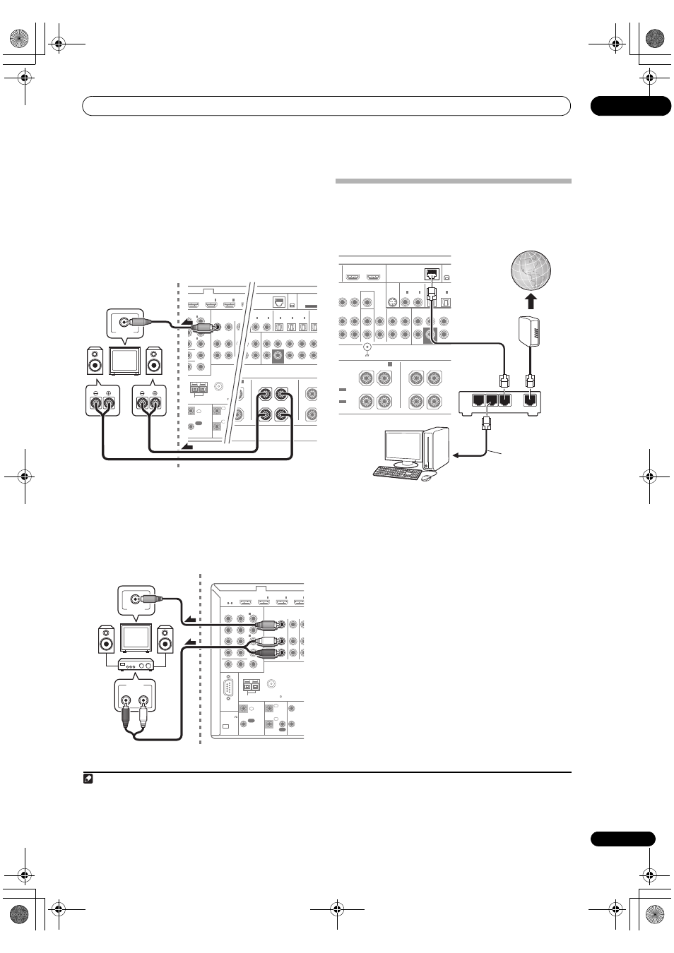
MULTI-ZONE setup using speaker terminals (ZONE 2)
You must select ZONE 2 in Speaker system setting on
page 85 to use this setup.
•
Connect a TV monitor to the VIDEO ZONE 2 OUT
jacks on this receiver.
1
You should have a pair of speakers attached to the
surround back speaker terminals as shown below.
Secondary MULTI-ZONE setup (ZONE 3)
•
Connect a separate amplifier to the AUDIO ZONE 3
OUT jacks and a TV monitor to the VIDEO ZONE 3 OUT
jack, both on this receiver.
You should have a pair of speakers attached to the sub
zone amplifier as shown in the following illustration.
Connecting to the network through
LAN interface
By connecting this receiver to the network via the LAN
terminal, you can listen to Internet radio stations.
2
Connect the LAN terminal on this receiver to the LAN
terminal on your router (with or without the built-in DHCP
server function) with a straight LAN cable (CAT 5 or
higher).
Turn on the DHCP server function of your router. In case
your router does not have the built-in DHCP server
function, it is necessary to set up the network manually.
For details, see Network Setup menu on page 87.
LAN terminal specifications
LAN terminal . . . . . . . . . . . . . . . . . . . . . . . . . . . . Ethernet jack
10BASE-T/100BASE-TX
Note
1 • COMPONENT VIDEO ZONE 2 OUT can be used to output clear images.
• The GUI screen is not displayed if only the COMPONENT VIDEO ZONE 2 OUT jack is connected.
• The video convert function does not work for ZONE 2. Connect the composite video and component video to the same types of jacks for the
inputs and outputs.
ENT VIDEO
NABLE
MONITOR OUT
ZONE 2 OUT
IN
ANTENNA
FM UNBAL 75
AM LOOP
ZONE2
OUT
ZONE3
OUT
DVD
IN
P
R
P
B
1
IN
BD
IN
1
IN
2
(DVD)
IN
2
(DVR/BDR)
IN
3
(VIDEO)
CONTROL
IR
1
T
IN
IN
IN
OUT
OUT
1
2
1
2
(
1
T
1
COAXIAL
OPTICAL
ASSIGNABLE
ASSIGNABLE
CD-R/TAPE
IN
CD
IN
DEO
OUT
OUT 2
IN
1
(DVD)
IN
1
(TV/SAT)
IN
2
(DVR/BDR)
IN
OUT
FRONT
CENTER SURROUND SURR BACK
(Single)
FH/FW
3
(VIDEO)
IN
2
(CD)
SUBWOOFER
LAN (10/100)
(OUTPUT 5 V
100 mA MAX)
ADAPTER P
PRE OU
XM
IN
SIRIUS
IN
L
CAUTION:
SPEAKER IMPEDANCE 6
Ω - 16 Ω .
ATTENTION:
ENCEINTE D'IMPEDANCE DE 6
Ω - 16 Ω .
SURROUND BACK
(Single)
B
HT/WIDE/
L
R
L
R
SU
VIDEO IN
R
L
Main zone
Sub zone (ZONE 2)
RS-232C
HDMI
ASSIGNABLE
COMPONENT VIDEO
ASSIGNABLE
MONITOR OUT
ZONE 2 OUT
IN
Y
ANTENNA
FM UNBAL 75
AM LOOP
ZONE2
OUT
ZONE3
OUT
DVD
IN
TV/
I
P
R
P
B
1
IN
BD
IN
1
IN
2
IN
3
1
4
(DVD)
IN
2
(DVR/BDR)
IN
3
(VIDEO)
CONTROL
EXTENSION
IR
12 V
TRIG
IN
IN
IN
OUT
OUT
1
2
1
2
(OUT
12 V
TOTA
150 m
(OUTPUT 5 V
150 mA MAX)
R
L
AUDIO IN
VIDEO IN
Main zone
Sub zone (ZONE 3)
2 To listen to Internet radio stations, you must sign a contract with an ISP (Internet Service Provider) beforehand.
COAXIAL
OPTICAL
ASSIGNABLE
ASSIGNABLE
CD-R/TAPE
IN
CD
IN
VIDEO
MONITOR
OUT
OUT
DVR/BDR
PHONO
IN
OUT
IN
OUT 1
(CONTROL)
OUT 2
IN
1
(DVD)
IN
1
(TV/SAT)
IN
2
(DVR/BDR)
FRONT
CENTER SURROUND
IN
2
(CD)
SUBWOOFER
LAN (10/100)
XM
IN
SIRIUS
IN
KERS
Wiring
SIGNAL
GND
SURROUND BACK
(Single
B
R
FRONT HEIGHT/WIDE/
L
R
L
TRUCTION
L
TABLE
MODE
OI
TABLE
WAN
3
2
1
LAN
LAN cable
(sold separately)
to LAN port
Router
Modem
Internet
PC
SC-1525_UXJCB.book 33 ページ 2010年4月20日 火曜日 午後7時32分