Painless Performance VORTEC 60211 User Manual
Page 9
F.
If your vehicle has a pressure type brake switch, you may use a relay as shown in Figure 6.3. The relay
must be a SPDT Relay and wired correctly or it could result in a dangerous situation with the vehicle. The
torque converter may not unlock.
G.
The wire labeled FUEL TEST is a test point for the fuel pump. After the vehicle has been wired and tested
OK, tape off this wire and store it in the harness.
H.
The wire labeled TACH (white) is the signal wire for a tachometer if used.
I.
The VSS output wire (green) sends out a signal to operate the electronic cruise control or speedometer if so
equipped.
6.2.2 Dash Section Connections
WIRE COLOR # OF POSITIONS LABELED CONNECT TO:
IN CONNECTOR
Gray, Grn/Wht, Blk/Wht, Org, Red 5 Fuel Relay Fuel Pump Relay
Green
VSS Output Speedometer
White Tach Tachometer
Purple, Brown Brake Switch Brake Switch
White Fuse Block Ignition Ignition Power
Table 6.1 Dash Section Connections
6.3
ENGINE GROUP INSTALLATION
The engine group is designed to be separated into left side (passenger) and right side (driver) sections. Each side is
tie-wrapped separately, BUT NOT LABELED. The left side of the engine has the connectors for the idle air control
and throttle position sensor, all of which ARE labeled. When you begin routing, FIRST separate the engine group
into left and right sections and place them accordingly.
6.3.1
Before you connect any wires, separate the tail section from the engine group and place it out of
the way.
6.3.2
Connect the two ring terminals labeled STARTER B+ with Red wires to the large battery terminal on the
starter solenoid.
6.3.3
Locate the two large ring terminals with Black and Blk/Wht wires and ground them to the engine.
6.3.4 Using
Figure 6.6-6.18, and the specific connections indicated in Table 6.2, connect the wiring as directed.
7
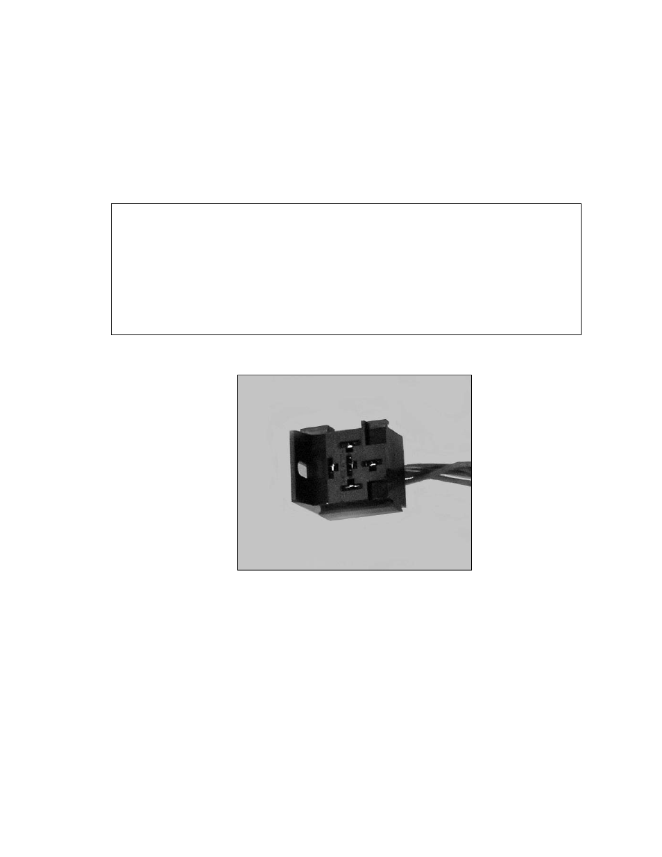
FIGURE 6.5 Fuel Pump Relay Connector