Painless Performance VORTEC 60211 User Manual
Page 7
5.4.4
Strip insulation away from wire. Only strip as much insulation off as necessary for the type of terminal lug
you are using.
Note: In the following step, make sure that the terminal is crimped with proper die in the crimping
tool. An improper crimp will not make a good connection. DO NOT OVER-CRIMP.
5.4.5
Crimp the terminal onto the wire.
5.4.6
Connecting the wires and connectors throughout the harness is a simple process. Make sure that each wire
is properly routed and then attached. DO NOT ATTACH THEN ROUTE AFTERWARD.
5.4.7
When all the wires are attached, tighten the mounts and ties to secure the harness permanently.
5.4.8
Attach the connectors to the computer. BEING VERY CAREFUL NOT TO BEND ANY PINS.
5.4.9
After all connections have been made throughout the harness, connect the battery to the vehicle.
CAUTION:
BE SURE THE IGNITION IS OFF WHEN YOU RECONNECT THE BATTERY
OR YOU WILL DAMAGE THE COMPUTER.
6.0
96-00 7.4 VORTEC SYSTEM WIRE HARNESS INSTALLATION INSTRUCTIONS
6.1
CONTENTS OF THE 60211 & 60216 WIRE HARNESS KIT
Take inventory to see that you have everything you are supposed to have in this kit. If anything is missing, contact the dealer
where you obtained the kit or contact Painless Performance at 800-423-9696. The kit should contain the following items:
~
The main wire harness with the connectors already on the ends of most of the wires.
~
Fuel Injection Installation Instructions P/N 90541 (This Booklet).
~
4” & 7” tie wraps.
6.2
SPECIFIC CIRCUIT CONNECTIONS
Note: If you have not already done so, read sections 4.0 and 5.0 of these instructions and think
through the installation of the harness before securing or cutting any wires. Wire color (Example: Blk/Wht) is
one wire with a stripe. The second color (the stripe) may not be bold. Observe all two-color wires closely.
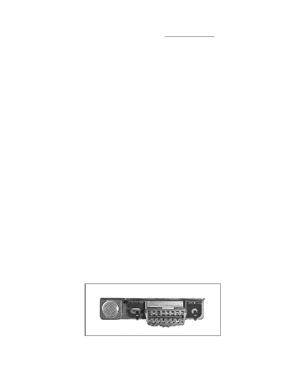
6.2.1 DASH SECTION INSTALLATION
The wires in this group consist of the diagnostic link connector (DLC) (SEE FIGURE 6.1), the check engine light
(pre-mounted into a mounting bracket), fuseblock/w fuses and relays, fuel pump relay connector/w relay and 7 other
wires.
Note: You may need to connect the check engine light wires to their mates in the wire harness.
CAUTION:
DO NOT MAKE ANY CONNECTIONS WHILE THE COMPUTER IS
PLUGGED
INTO
THE
HARNESS.
5
FIGURE 6.1 DLC Connector & Check Engine Light