Painless Performance VORTEC 60211 User Manual
Page 13
6.4
TAIL SECTION INSTALLATION
6.4.1
Locate the tail section that you earlier separated from the engine group. Begin routing it towards
the rear of the vehicle. Be sure to avoid all sharp edges, moving or hot parts, or anything else that
may damage the harness.
6.4.2
If you are using the 4L80E transmission, route the 13-position connector to the transmission and attach it.
Route the input shaft speed sensor connector to the transmission and attach it.
6.4.3
Take the connector for the Vehicle Speed Sensor (VSS) and connect to the Vehicle Speed Sensor.
6.4.4
Take the gray wire labeled FUEL PUMP and route it to the fuel pump. This is the power wire for the fuel
pump.
6.4.5
Tail Section Connections
WIRE COLOR # OF POSITIONS LABELED CONNECT TO:
IN CONNECTOR
11
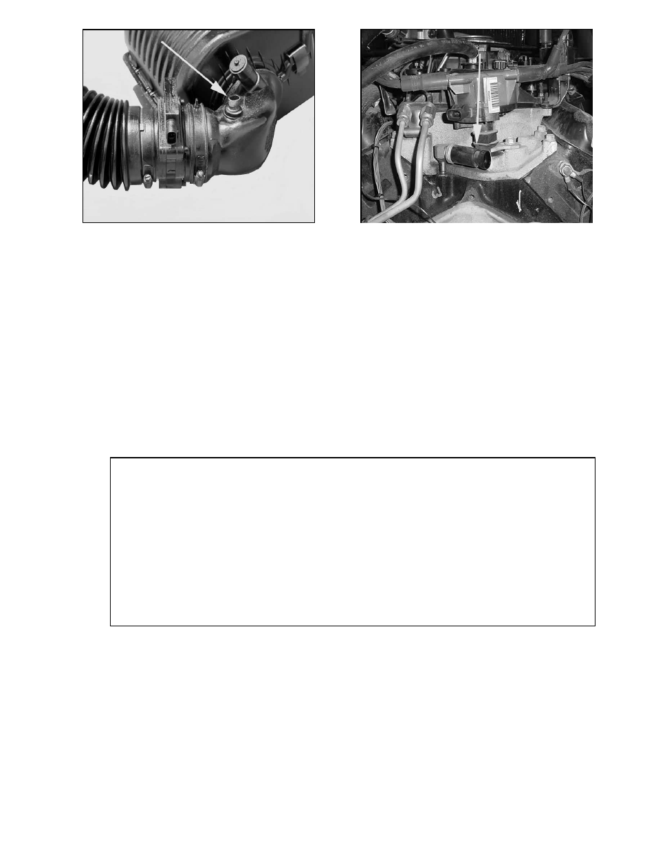
FIGURE 6.17 IAT Sensor
Red/Black, Blue/White
Purple/White, Green/Black
Lt. Green, Yellow/Black, Yellow,
Red/Black, Lt. Blue/White, Pink,
Pink/Black, Black, Red, Blue,,
Tan/Black, Brown
Gray
2
2
13
VSS Input
VSS Output
Trans.
Fuel Pump
Vehicle Speed Sensor
Vehicle Speed Sensor
Transmission
Fuel Pump Power Terminal
TABLE 6.4 Tail Section Connections
FIGURE 6.18 Fuel Pump/Oil PressureSwitch