0 configuration, 1 configuring the hardware dip switches, 2 configuring dip switch s1 – Patton electronic COPPER LINK 2174 User Manual
Page 14: Configuration, Configuring the hardware dip switches, Configuring dip switch s1
14
4.0 CONFIGURATION
The Model 2174 has eight DIP switches (S1) for configuring the unit for a
wide variety of applications. This section describes switch locations and
explains the different configurations.
4.1 CONFIGURING THE HARDWARE DIP SWITCHES
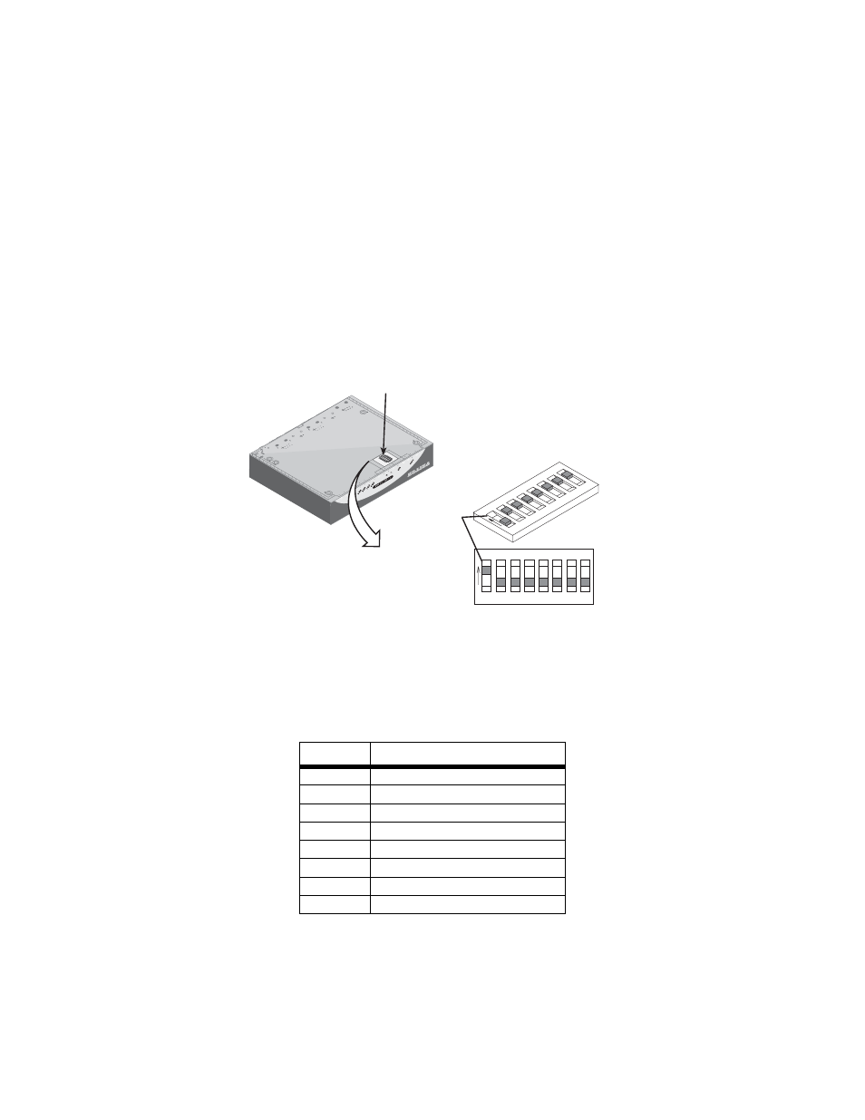
The DIP switches are externally accessible from the underside of the
Model 2174. Figure 7 on page 14 shows the orientation of the DIP
switches in the On and Off positions.
Figure 7.
DIP switch orientation
4.2 CONFIGURING DIP SWITCH S1
DIP switch S1 is where you configure the CopperLINK line. The following
tables describe the configuration for the 2174.
Table 1:
S1 Summary
Position
Description
S1-1
Local/Remote Configuration
S1-2
Line Rate/Symmetry
S1-3
Line Rate/Symmetry
S1-4
Reserved
S1-5
SNR Margin
S1-6
Reserved
S1-7
Reserved
S1-8
Reserved
Push toggle up
for ON position
Switch toggle
Push toggle
down for
OFF position
S1
1 2 3 4
ON
1 2
3 4
ON
S1
S1
5 6 7 8
5 6
7 8