Poulan 172777 User Manual
Page 12
12
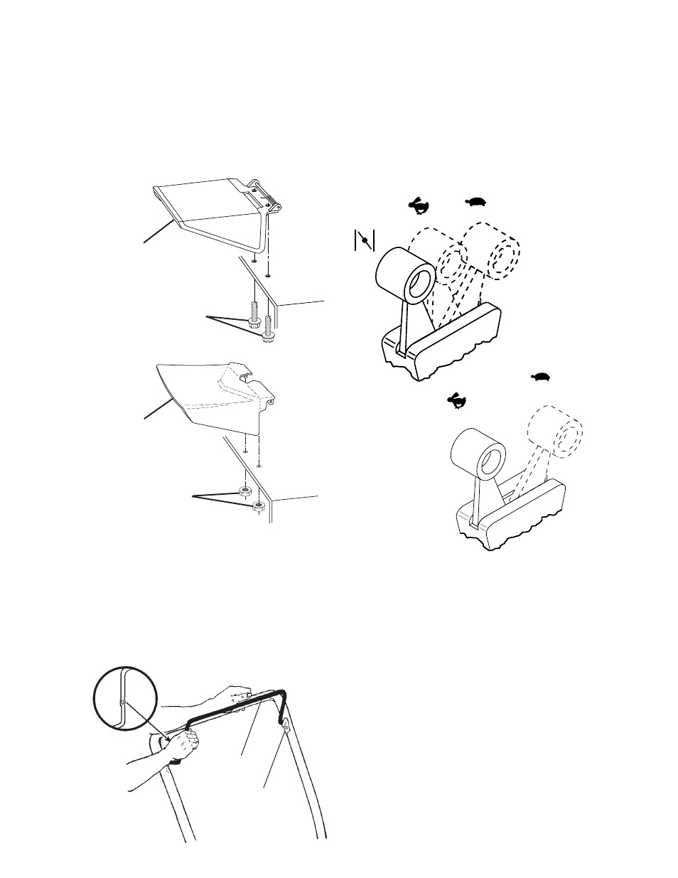
Locknuts
Discharge
guard
MODELS WITH SPRING LOADED
DISCHARGE GUARD
• Place discharge guard on top of lawn
mower discharge opening.
• Install two (2) hex self-tapping screws
through housing and into guard mount-
ing bracket or, install two (2) 1/4-20
locknuts (If equipped). Tight en securely.
SCREW MOUNTED TYPE
NUT MOUNTED TYPE
ASSEMBLE REMOTE THROTTLE
CONTROL TO ENGINE
(ON MODELS SO EQUIPPED)
(USE HARDWARE GROUP “E”)
If your mower does not have a remote throttle
control, go on to “ASSEMBLE ENGINE ZONE
CONTROL CABLE TO ENGINE”.
• First, move lever on remote throttle
control to the CHOKE (if equipped) or
FAST/START position.
CHOKE
FAST/START
Determine the manufacturer and brand or
type engine on your lawn mower and follow
the appropriate in struc tions that follow.
MODELS WITH BRIGGS & STRATTON
CLASSIC OR SPRINT AND TECUMSEH
ENGINES
NOTE: Tecumseh engines have cable
mounting clamp and screw preassembled
on engine.
• At en gine carburetor, insert wire “Z”
bend of throttle control into hole of
speed lever (use inner hole on Briggs &
Stratton engine).
• (Briggs & Stratton only) Assemble di-
ecast clamp and #10 x 5/8 screw loosely
to engine.
• Position throttle cable under clamp and
push cable towards speed lever until speed
lever touches boss. Hold cable at this po-
sition and tighten clamp screw securely.
INSTALL CONTROL BAR
(NO HARDWARE REQUIRED)
• Position control bar so fl attened sec tion
with hole is on opposite side of upstop
bracket.
• Insert one end of control bar into hole be-
hind upstop bracket. Carefully push in on
opposite end of control bar and insert into
formed hole on inside of upper handle.
Upstop
bracket
Control
bar
Hex head
self-tapping
screws
Discharge
guard