Poulan 172777 User Manual
Page 11
11
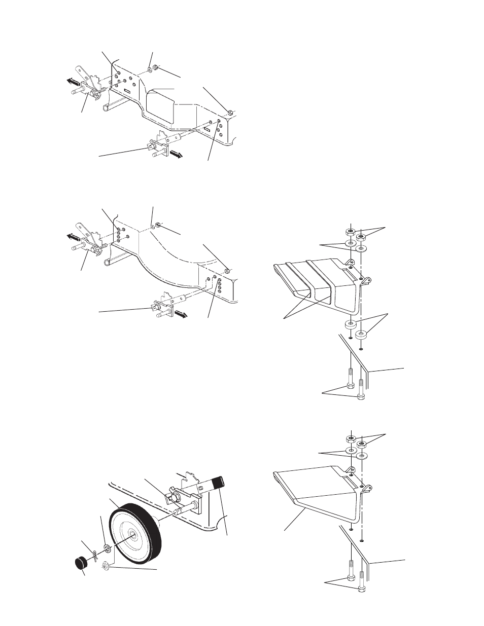
SIDE DISCHARGE MOWERS
REAR DISCHARGE MOWERS
ASSEMBLE WHEELS TO ADJUSTER
AXLE ARMS
• Secure each wheel with fl at washer
and retainer spring or fl ange locknut (if
equipped with threaded axle).
• Assemble adjustment knobs to ad just er
levers by press ing or tapping lightly.
• If your mower is equipped with hub caps,
install by pressing or tap ping lightly until
hub cap snaps se cure ly over fl at wash er.
TYPE I
Right rear/left front
height ad just er
TYPE II
Right front/left rear height ad just er
Tab hole
Tab hole
1-1/4" Washer (If supplied)
Locknuts
TYPE I
Right rear/left front
height ad just er
TYPE II
Right front/left rear height ad just er
Tab hole
Tab hole
1-1/4" Washer (If supplied)
Locknuts
Wheel
Flat washer
Retainer
spring
Axle arm
Hubcap (If epuipped)
Flange locknut
(If equipped with
threaded axle arm)
Adjustment
knob
INSTALL DISCHARGE GUARD
(SIDE DIS CHARGE MODELS ONLY)
(USE HARDWARE GROUP “D”)
If your mower is a rear discharge mower,
go on to “INSTALL CON TROL BAR”.
MODELS WITH BOLT-ON GUARD
NOTE: If your discharge guard has ribbing
as shown in the illustration below, there
are two (2) spacers which must be placed
between guard and mower housing.
• Place discharge guard on top of lawn
mower discharge opening.
• Install two (2) 1/4-20 short hex bolts
through housing and discharge guard.
• Install two (2) 3/4" washers and two
(2)1/4-20 locknuts. Tighten securely.
BOLT-ON GUARD WITHOUT RIBBING
BOLT-ON GUARD WITH RIBBING
Hex bolts
Washers
Discharge
guard
Locknuts
Hex bolts
Washers
Spacers
Discharge
guard
ribbing
Locknuts