Pin assignments – Powerware BestLink IPK-0319 User Manual
Page 36
Appendix
30
BestLink SNMP/WEB Adapter User’s Guide
:
LTM-1343 B Draft 10/03/2001
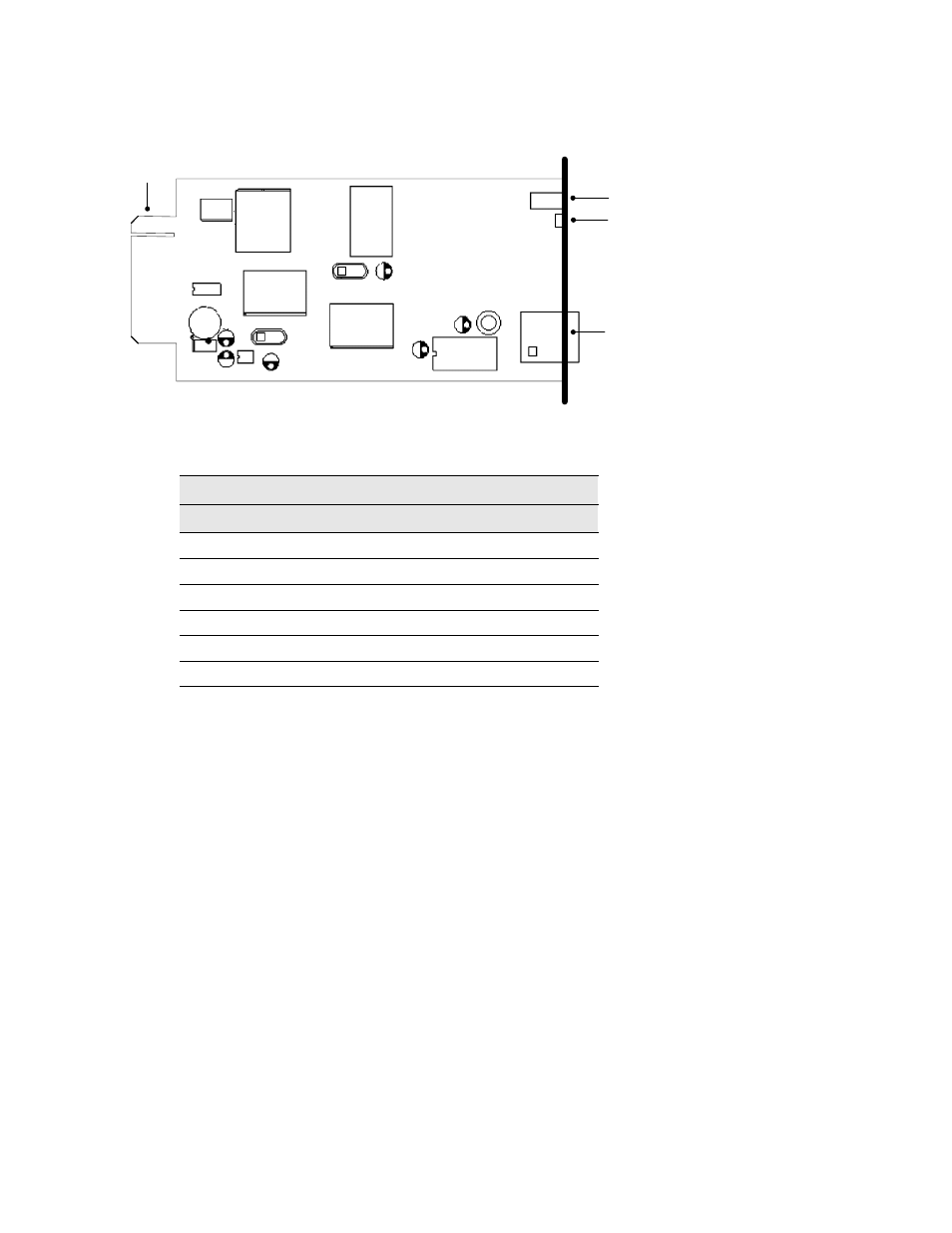
Pin Assignments
DIP Switch
LEDs
Network
Connector
PCB Edge
Connector
Figure 14. Internal BestLink Adapter Component Layout
Table 5. PCB Edge Connector Pin Assignments
Bottom Side
Component Side
Pin Number
Function
Pin Number
Function
1
GND
2
9 Vdc
2
TxD_UPS
4
RxD_UPS
5
TxD_PC
6
RxD_PC
7
NC
8
Short to Pin 10
9
GND
10
Short to Pin 8
11-25
NC
12-26
NC