Porter-Cable PCB270TS User Manual
Page 14
– 14 –
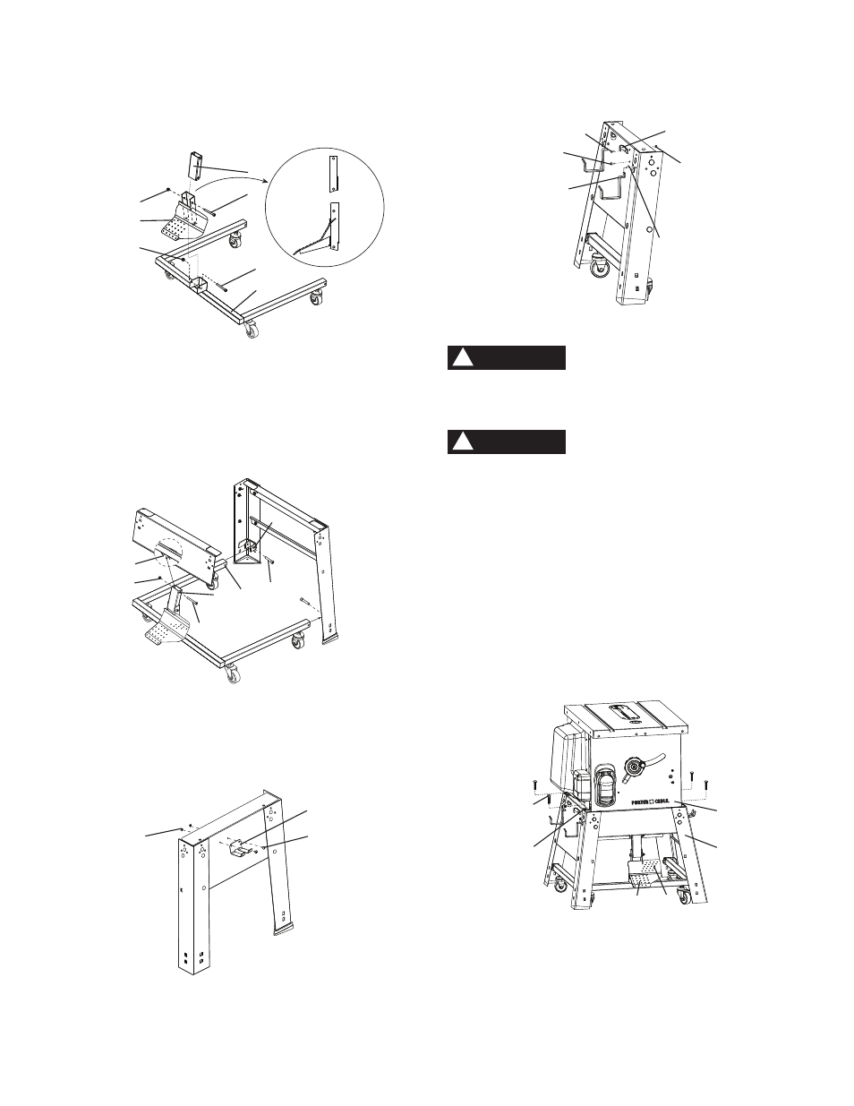
9.
Bag “I” - Mount the pedal (1) to the caster bracket
(2) by using the longest bolt (3) and nut (4), and
attach the link (5) to pedal (1) with bolt (6) and nut
(4) by 6 mm hex key supplied.
Fig. F
10.
Bag “I” - Attach the left / right rear tubes (8) of
caster bracket into the brackets (9) of the rear legs
by using two short bolts (10). Attach the link (5) into
the bracket (11) with bolt (6) and nut (4).
NOTE: Do not over tighten bolts. The caster
assembly will be difficult to operate if the bolts are
too tight.
Fig. G
NOTE: The front right / left legs have been removed
from this drawing for illustration purposes only.
11.
Bag “J, K” - Attach miter gauge storage (12) to the
right leg support by using two short screws (14) and
nuts (15).
Fig. H
12.
Bag “J, K” - Attach power cord storage (16) to the
left leg support by using two long screws (18) and
nuts (15).
9
8
10
6
11
4
5
13.Insert the rip fence storage (20) into slots (21) of the
left leg support, tighten by using two of six screws
(22).
Fig. I
NOTE: Make sure all screws and nuts are tight and stand
is on a stable surface before mounting saw.
Although compact, this saw is heavy and should be
lifted with care. Get the assistance of someone to lift
and move the saw.
For your safety, never connect plug to power source
receptacle until all assembly and adjustment steps are
complete, and you have read and understood the safety
instructions.
ASSEMBLING TABLE SAW TO STAND (FIG. J)
1. Lift the saw body (1) and place on the stand (2),
aligning the mounting grooves (3) of the saw base
with the four mounting holes on the top plate of
stand.
2.
Bag “P” - Attach the table saw to the stand with four
hex head bolts (4).
3. Tighten all mounting bolts with a wrench.
Fig. J
MOVING TABLE SAW AND STAND (FIG. J)
1. Tread on the area (5) of pedal to lift the saw and
stand when stand legs contacting the level surface.
2. Move the saw and stand to the desired location by
the caster assembly for operation or storage.
3. Tread on the area (6) of pedal to put the saw and
stand on the ground.
WARNING
!
4
3
1
2
5
6
WARNING
!
14
12
15
21
16
18
22
20
15
5
6
3
2
4
1
4
Right side
view