Input select, Main menu, Continued) – Panasonic BT-LH1700WP User Manual
Page 21
21
The underlined values are factory preset setting values.
*1 “AUTO” is set when the monitor is shipped from the factory, but if there are concerns about noise etc. from outside the
input signal, we recommend assigning specific format.
g COMP.
The following menus are switched by selecting “RGB-COMP.” in “YP
B
P
R
/RGB” in the “INPUT SELECT” menu.
The underlined values are factory preset setting values.
*1 “EXECUTING” is displayed while “AUTOSETUP” is being executed, and “COMPLETE” is displayed when
“AUTOSETUP” is completed.
If “AUTOSETUP” cannot be completed, “INCOMPLETE” is displayed.
*2 Each RGB-COMP. input compatible format can be adjusted.
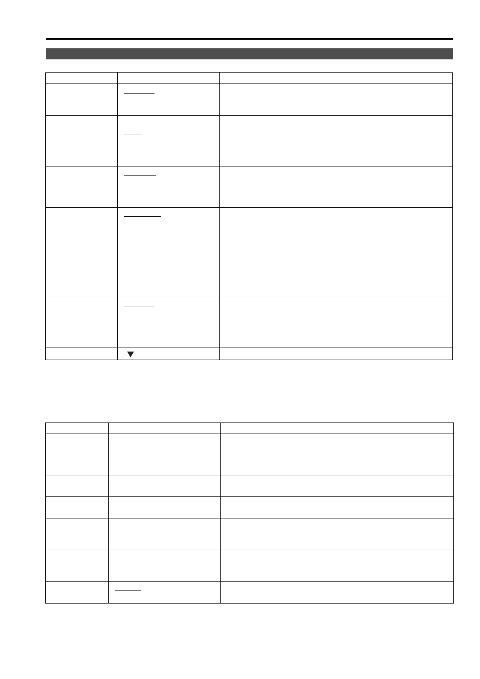
INPUT SELECT
Sub menu
Settings
Explanation
VIDEO / Y/C
Used to select the input format for VIDEO and Y/C input.
*1
Either NTSC or PAL is automatically selected.
NTSC
PAL
NTSC SETUP
<75>
<00>
Selects the NTSC setup level.
<75>
Select this when using with a setup signal of
7.5 IRE. (The inner parts of the monitor are set
to the 7.5 IRE setup level to suit the black level)
<00>
Select this when there is no setup level signal.
YP
B
P
R
/RGB
B P R > Selects either YP B P R (Component) or RGB input mode. B P R > Selects the YP B P R signal. COMPONENT Selects YP B P R (Component) signal input level. When the signal level specified in SMPTE is B , P R = 0.7 Vp-p. Select this when connecting a betacam or Select this when connecting a betacam or similar RGB SYNC Selects the SYNC when using RGB-VIDEO input. Select when a synchronizing signal is Select when an external synchronizing signal is COMP. Performs analog PC settings. (Refer to “COMP.” below) Sub menu Settings Explanation AUTOSETUP *1 Screen automatic adjustment is performed when “RGB- B P R /RGB” in the “INPUT SELECT” menu. “AUTOSETUP” is performed if a different screen is H POSITION <0–60> Used to adjust the picture display position in the horizontal *2 V POSITION <0–60> Used to adjust the picture display position in the vertical *2 PHASE <0–31> J page 22) Used to adjust the clock phase with 1/32 clock phases. *2 CLOCK <700–1800> J page 22) Used to adjust the sampling clock in dot units. *2 WXGA/XGA Switches between WXGA and XGA. Main Menu (continued)
LEVEL
Chroma 100 IRE P
simliar devices set to 7.5 IRE. (The inner parts
of the monitor are set at 7.5 IRE setup level to
suit the black level)
devices that are not setup to the IRE level.
superimposed on the G signal.
received in synchronization.
COMP.” is selected in “YP
displayed, and “YES” is selected.
(Factory preset settings: 30)
direction.
(Factory preset settings: 30)
direction.
(Factory preset settings:
(Factory preset settings: