Connecting amplifier or system component, Before use, Connecting a digital amplifier or system component – Panasonic DIGA DMR-E75V User Manual
Page 12: Connecting an analog amplifier or system component
Before Use
12
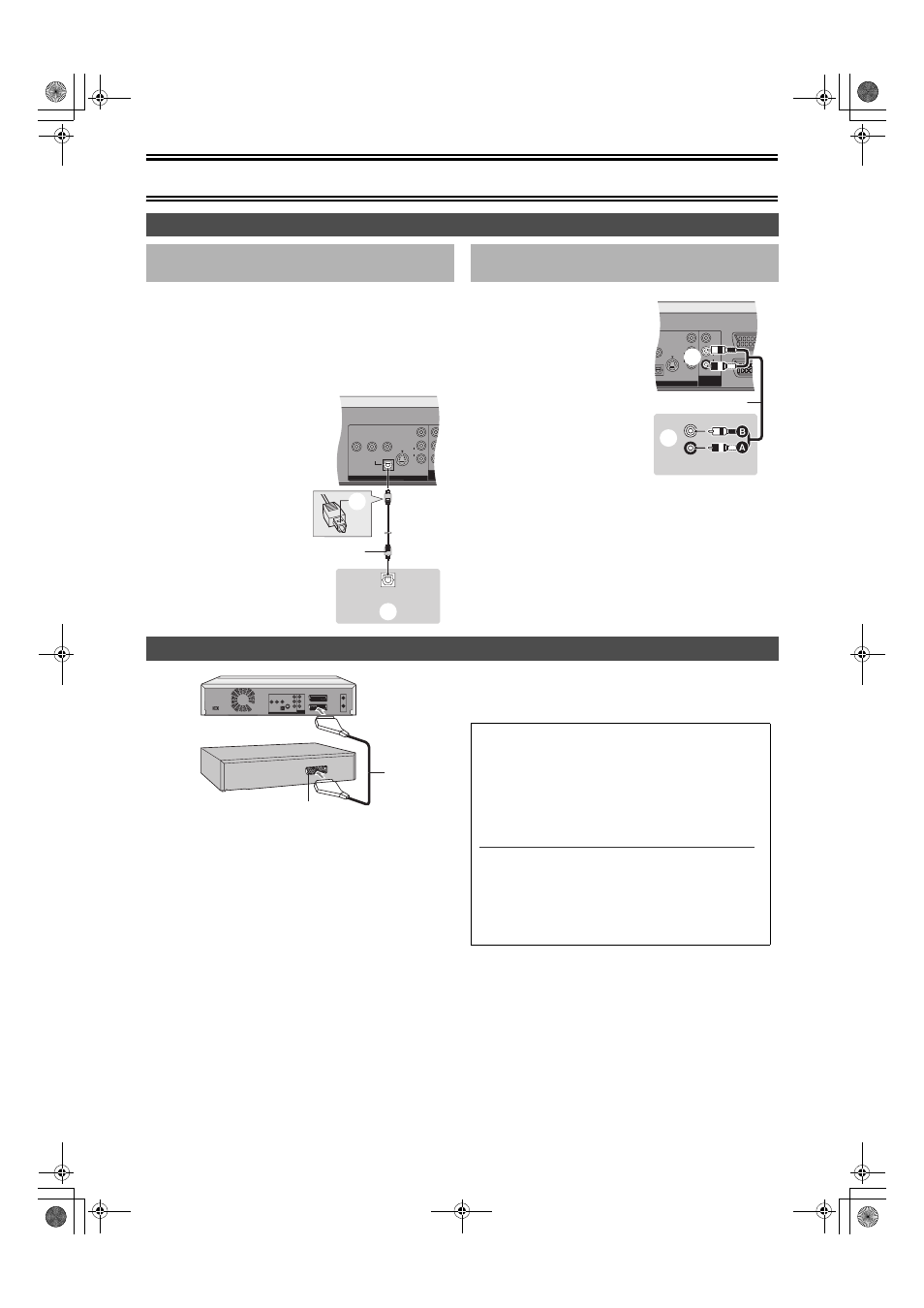
Connect an amplifier with a Dolby Digital, DTS and MPEG decoders.
(
≥Use an optical digital audio cable.
≥Change the settings in “Digital Audio Output” (
≥You cannot use DTS Digital Surround decoders not suited to DVD.
≥Even if using this connection, output will be only 2 channels when
playing DVD-Audio.
(1) Decoder, satellite receiver or digital receiver (not supplied)
(2) 21-pin Scart socket
(3) 21-pin Scart cable (not supplied)
Connect a 21-pin Scart cable (not supplied) to the AV2 21-pin
Scart socket on this unit and to the 21-pin Scart socket on the
decoder, satellite receiver or digital receiver.
Connect the mains lead of decoder, satellite receiver or digital
receiver to an AC mains socket.
≥If you connect an other equipment with RGB output capability to the
AV2 socket on this unit, the output signal of the equipment must be
set to RGB when you have set “AV2 Input” to “RGB (Not NTSC)”.
(
≥The decoder here means the device used to decode scrambled
broadcasts (Pay TV).
≥Change the “AV2 Input” and “AV2 Connection” settings in the
SETUP menu to match the connected equipment. (
Connecting amplifier or system component
∫ Connecting a digital amplifier or system
component
OPTICAL
DIGITAL AUDIO OUT
(PCM/BITSTREAM)
VIDEO
S-VIDEO
AUDIO
R
L
AU
DVD OUT
DVD
COMMO
COMPONENT VIDEO OUT
(PROGRESSIVE/INTERLACE)
Y
P
B
P
R
OPTICAL IN
(5)
(1)
(3)
(2)
(4)
(1) Rear panel of this unit
(2) Insert fully, with this side
facing up. (Do not bend
when connecting.)
(3) Optical digital audio
cable (not supplied)
(4) Optical digital input
(5) Amplifier’s rear panel
∫ Connecting an analog amplifier or system
component
AV1 (TV)
AV2 (DECODER/EX
VIDEO
S-VIDEO
VIDEO
AUDIO
R
L
AUDIO
R
L
DVD OUT
DVD/VHS
COMMON OUT
O OUT
RLACE)
P
R
(2)
(3)
(1)
AUDIO IN
(5)
(4)
R
L
(1) Rear panel of this unit
(2) AUDIO OUT (L/R)
(3) Audio cable (not supplied)
A Red (R)
B White (L)
(4) Audio input (L/R)
(5) Amplifier’s rear panel
Connecting a decoder, satellite receiver or digital receiver
(1)
(2)
(3)
AV Link Function
(This function is not available in Australia.)
If you connected the television to the AV1 terminal and the
decoder to the AV2 terminal on this unit, press [0]
i[ENTER].
(“DVD” appears on the unit’s display.)
Press again to cancel. (“TV” appears on the unit’s display.)
≥If the TV is compatible with RGB input, the RGB output
signal from the decoder can also be output from the main
unit the same way.
Note
[RGB] means separate Red/Green/Blue colour signals. If your
TV is equipped with RGB input capability, by connecting with
a fully wired 21-pin Scart cable you can see video using RGB
output on this unit (PAL video only) (
To output in RGB select “RGB (without component)” from
“AV1 Output” in the SETUP menu (
l 45).
75VGN.book 12 ページ 2004年7月21日 水曜日 午前11時54分