1 general, 2 general start-up measurement, Supply check – Philips DVD763SA/001 User Manual
Page 25: Table, Clock check, Audio mute check, 3 audio dac and amplifier, 4 video output and buffer amplifier, 5 play and 16/9 detection
Diagnostic Software, Trouble Shooting and Test Instructions
EN 40
5.
5.9
Test Instruction Front Display and Audio/
Video Board
These test instruction is designed specifically for SACD 2002
single disc models which has the following outputs:
•
6 Channel Audio output
•
Coaxial / Optical digital output
•
CVBS
•
Component output YUV
•
SVHS
•
Double SCART output
•
Front Display
5.9.1
General
•
All the waveforms measurement carried out in these test
instruction will be base on the testpoint indicated in the
A/V Board and Front Display schematic diagram in the
Service manual.
•
Impedance of the measuring-equipment should be > 1M
Ω
•
Most of the tests can be done using either the Diagnostic
software “ Player script” which can be found in the chapter
“Diagnostic Software description and troubleshooting” or
the Menu interface using the Service PC with a terminal
emulation program ( e.g. Window Hyperterminal ) where it
is possible to control the execution of the Diagnostic Nuclei
•
Setup for the measurement will be done in set level with all
modules connected as shown in the Wiring Block diagram.
5.9.2
General Start-Up Measurement
Supply Check:
Before starting the measurement,ensure that all power supply
are connected to the A/V and Front Display board via
conn.1420 and 1127 respectively.
Clock Check
Ensure the present of the clock to the DAC and the slave
µ
P.
Audio Mute Check
Measure the Audio mute voltage input at pin 22 of connector
1421
To toggle between ON and OFF,use the following commands:
5.9.3
Audio DAC And Amplifier
Ensure that the Audio mute signal is OFF
To check the DAC and buffer amplifier,send the following
commands.
The audio signal ( sine or pink noise ) will also be present on
the digital output ( SPDIF ).This can be checked by connecting
digital signal to an amplifier with digital input.
Check the I2S and audio signal at the following testpoints:
All waveforms can be refered to the A/V board schematic
diagram.
5.9.4
Video Output And Buffer Amplifier
Check DC output-level at all video cinch output : 1.0V DC
±
10%
Generate a color bar using the following software commands:
Check the video outputs at the following testpoints:
ll waveforms can be refered to the A/V board schematic
diagram.
5.9.5
Play and 16/9 Detection
Check DC voltage at S-VIDEO-CHROMA output (pin 4) with a
6k8 ohm load and SCART connector 1403 (pin 16) and change
the SCART0 and SCART1 input using the following
commands:
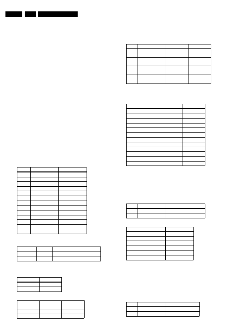
Pin nr.
A/V Board
Front Display
Voltage
Conn. 1420
Conn. 1127
1
+3V3_Power
-
2
+3V3_Power
-
3
GND
-
4
+12V_Power
-
5
+12VSTBY
-
6
GND
+5VSTBY
7
+5VSTBY
+12V_Power
8
GND
-32V_Power
9
-12V_Power
-
10
GND
-
11
-32V_Power
-
12
-
Clock Name Testpoint Frequency
PCM_CLK
I117
11.2896MHz
±
0.02% tolerance
XOUT
S1
8MHz
±
0.2% tolerance
Status
Value
AudioMuteOn
HIGH (>3V)
AudioMuteOff
LOW (<3V)
Ref.#
Command
Name
Remarks
19a
AudioMuteOn
Audio Mute On
19b
AudioMuteOff
Audio Mute Off
Ref.#
Command Name
Remarks
Audio output
21a
AudioSineOn
Audio Sine
signal ON
Sine,1Khz on
stereo
----
Press stop button
Audio Sine
signal OFF
No waveform
20a
AudioPinkNoiseOn Audio
Pinknoise ON
Pink Noise on
6 channels
20b
AudioPinkNoiseOff Audio
Pinknoise OFF
No waveform
Name
Testpoint
PCM_LRCLK
I115
PCM_SCLK
I116
PCM_CLK
I117
SDT1
I114
SDT2
I112
SDT3
I110
DIG_OUT
I499
STEREO L/R OUT
I330 / I333
FRONT L/R OUT
I336 / I339
SURROUND L/R OUT
I348 / I351
CENTRE OUT
I345
SUB WOOFER L/R OUT
I342
Ref.#
Command Name
Remarks
23a
VideoColDencOn
Colour DENC ON
23b
VideoColDencOff
Colourbar DENC OFF
Name
Testpoint
GREEN_Y
I502
BLUE_U
I491
RED_V
I494
CVBS out_Mono
I480
C_Mono
I483
Y_Mono
I482
Ref.#
Command Name
Remarks
25a
VideoScartLo
Sends out 0V
±
0.5V
25b
VideoScartMi
Sends out 6V
±
10%