Output wiring – Lochinvar Harmony User Manual
Page 7
7
WIRING A SETBACK
• The Setback feature can be used to provide the Harmony with a
lower temperature Set Point when less load is required.
• A typical use for Setback is to lower the system temperature during
the night or on the weekends when a building is unoccupied, but a
minimum level of heat is still required.
• The Setback feature can not be used with External Set Point (4-20mA
EMS-control) or Reset operation (see Startup Settings, pg. 11).
• To adjust the amount of Setback see pg. 19.
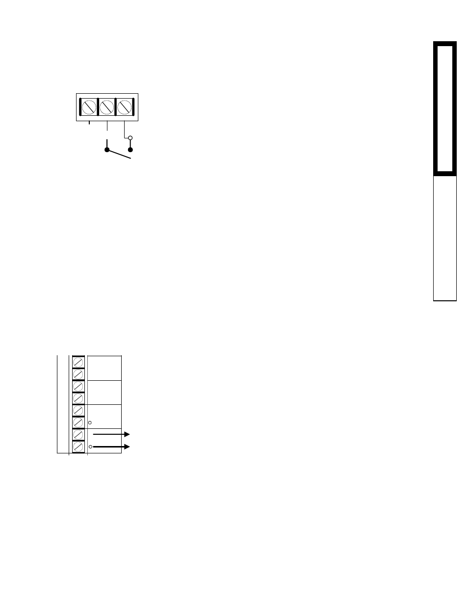
• The Setback signal is wired into the EMS terminals (Terminals
SIGNAL and SHIELD).
• The Setback signal must be a dry contact only. No voltage can be
placed across the EMS SIGNAL and SHIELD terminals.
• When the EMS SIGNAL and SHIELD are closed, the Setback is
enabled and the Harmony will hold the lower Set Point. The lower Set
Point will appear on the main display indicating this condition.
• When the closure is removed, the Harmony will revert to the higher
saved Set Point.
Note: The Setback is not equivalent to the 4-20mA input, even though
both wire into the EMS terminals. The 4-20mA input requires a 4-
20mA source which changes the Set Point in one degree increments.
The Setback provides a single lower Set Point.
CONNECTING AN OUTDOOR SENSOR
For Reset Operation
• To enable the reset function, see System Startup settings, pg. 11.
For Outdoor Cutoff
• The Harmony will disable all stages when the outdoor temperature is
above the adjustable Outdoor Cutoff temperature.
• This feature will automatically be activated when an outdoor sensor
is connected.
• To adjust the Outdoor Cutoff temperature see pg. 26.
Installing the sensor
• For outdoor sensor use the outdoor sensor.
• Locate the sensor in the shade on the north side of the building
• Be sure the location is out of direct sunlight, and away from doors,
windows, exhaust fans, vents, or other possible heat sources
• The sensor should be mounted at least 4 inches away from the
building wall and approximately 10 feet above ground level
• The sensor wires can be extended up to 500' using shielded 2
conductor cable (Belden #8760 or equivalent).
• Do not run sensor wires in conduit with line voltage wiring.
• Temperature sensors have no polarity. Connect either wire from the
outdoor sensor to one of the Harmony terminals marked OUTDOOR
(Terminals A11&A12).
• Connect the other sensor wire to the other OUTDOOR terminal.
• Connect the shield to the circled terminal OUTDOOR (Terminal A12)
with one of the sensor wires.
OUTPUT WIRING
INSTINSTINSTINSTINST
ALLAALLAALLAALLAALLA
TIONTIONTIONTIONTION
INPUT WIRINGINPUT WIRINGINPUT WIRINGINPUT WIRINGINPUT WIRING
EMS INPUT
+
SIGNAL
SHIELD
Dry Contact
Setback
Signal
NETWORK
SYSTEM
PROVE
+
S
A5
A6
A7
A8
A9
A10
A11
A12
OUT
TEMP
T
To Outdoor
Sensor Mounted
in Shade