Ems input default - setback, Selecting the output type, Selecting the modulating mode default - normal – Lochinvar Harmony User Manual
Page 12: Setback, External set point (4-20ma ems-control)
12
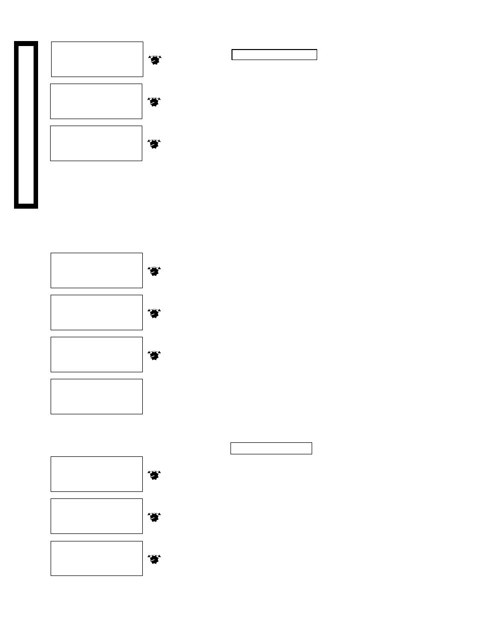
- MODULATING MODE
>NORMAL
PARALLEL
- MODULATING MODE
NORMAL
>PARALLEL
- MODULATING MODE
NORMAL
>PARALLEL
PRESS TO SELECT
ADJUST
Press to
select
Normal
PRESS TO SELECT
ADJUST
or turn
to scroll
down
PRESS TO SELECT
ADJUST
Press to
select
Parallel
EMS INPUT
Default - Setback
Not available for Reset Sensor Types
Setback
• This default setting allows the Set Point to be adjusted either
manually at the panel, or by a Visual Gold upgrade for remote
communications.
• If desired, a dry contact switch can be wired across the EMS INPUT
terminals SIGNAL and SHIELD to allow the panel to hold a lower
temperature Set Point when less load is required. To adjust the
amount of Setback, see pg. 19.
• When selecting Setback, there is no requirement for any wiring
across the EMS INPUT terminals. DO NOT select EMS-Control
unless your system meets the requirements below.
External Set Point (4-20mA EMS-Control)
• For this option, an EMS system must provide a 4-20mA signal to
automatically change the Set Point based on pre-programmed
system parameters.
• An active signal must be wired into the EMS Harmony terminals. If
the Harmony does not receive a signal between 3.9mA and 20.1mA,
it will NOT activate any stages.
• If your system meets the above two criteria, see pg. 28 to complete
the EMS-control setup.
SELECTING THE OUTPUT TYPE
• The Harmony has two output cards, one for stages A & B, and one
for stages C & D.
• Both output cards must be programmed for the appropriate mode of
operation.
• Outputs can be configured for 4-20mA operation (current) or the
voltage range can be selected (0-5V, 0-10V, 1-5V, 2-10V).
• Check the modulating motor to determine its control requirements.
• Select the appropriate Output Type for stages A & B. The Harmony
will then automatically bring up the screen for stages C & D.
• Select the appropriate Output Type for stages C & D.
• If different types of burners are being used, stages C & D can be
selected to have a different Output Type than stages A & B.
SELECTING THE MODULATING MODE
Default - Normal
• Most boilers run more efficiently as their modulation increases.
Therefore, for most systems, it is more energy efficient to run one
boiler in high than several boilers at lower modulation. If your
system is of this type, select Normal.
• There are some systems were it may be more energy efficient to run
several units at lower modulation than one at high. If that is the case
select Parallel.
IMPORTANT: Do not select EMS-Control
unless an appropriately configured signal
from an EMS system is correctly wired into
the Harmony. For additional details, see pg.
5 for wiring, and pg. 28 for EMS-Control
setup.
PRESS TO SELECT
ADJUST
Press to
select
Setback
---- EMS INPUT ----
>Setback
EMS-Control
---- EMS INPUT ----
>Setback
EMS-Control
or turn
to scroll
down
---- EMS INPUT ----
Setback
>EMS-Control
PRESS TO SELECT
ADJUST
Press to
select
EMS
PRESS TO SELECT
ADJUST
SYSYSYSYSY
STEM STSTEM STSTEM STSTEM STSTEM ST
ARARARARAR
TUPTUPTUPTUPTUP
- OUTPUT TYPE A&B -
>4-20ma
0-10v
0-5v
- OUTPUT TYPE A&B -
4-20ma
>0-10v
0-5v
- OUTPUT TYPE A&B -
4-20ma
>0-10v
0-5v
- OUTPUT TYPE C&D -
>4-20ma
0-10v
0-5v
PRESS TO SELECT
ADJUST
Press to
select
4-20ma
PRESS TO SELECT
ADJUST
or turn
to scroll
down
PRESS TO SELECT
ADJUST
Press to
select
new
Repeat
process for
Stages C&D