6 ct table for lib, Table 3 wiring configuration for lib 1, Ct table for lib – Liebert Distribution Monitoring LDM User Manual
Page 17: Table 3, Wiring configuration for lib 1
Installation
13
4.6
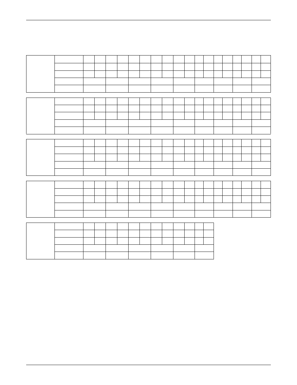
CT Table for LIB
Tables 3 and 4 show the CT assignments for 10 output breaker CTs and three subfeed breaker CTs
with neutral and ground being monitored.
Table 3
Wiring configuration for LIB 1
Connector
TB1
Pins
18
17
16
15
14
13
12
11
10
9
8
7
6
5
4
3
2
1
-
+
-
+
-
+
-
+
-
+
-
+
-
+
-
+
-
+
Wire Color
B
W
B
W
B
W
B
W
B
W
B
W
B
W
B
W
B
W
CT
CT9
CT8
CT7
CT6
CT5
CT4
CT3
CT2
CT1
Phase
A3
N2
C2
B2
A2
N1
C1
B1
A1
Connector
TB2
Pins
18
17
16
15
14
13
12
11
10
9
8
7
6
5
4
3
2
1
-
+
-
+
-
+
-
+
-
+
-
+
-
+
-
+
-
+
Wire Color
B
W
B
W
B
W
B
W
B
W
B
W
B
W
B
W
B
W
CT
CT18
CT17
CT16
CT15
CT14
CT13
CT12
CT11
CT10
Phase
B5
A5
N4
C4
B4
A4
N3
C3
B3
Connector
TB3
Pins
18
17
16
15
14
13
12
11
10
9
8
7
6
5
4
3
2
1
-
+
-
+
-
+
-
+
-
+
-
+
-
+
-
+
-
+
Wire Color
B
W
B
W
B
W
B
W
B
W
B
W
B
W
B
W
B
W
CT
CT27
CT26
CT25
CT24
CT23
CT22
CT21
CT20
CT19
Phase
C7
B7
A7
N6
C6
B6
A6
N5
C5
Connector
TB4
Pins
18
17
16
15
14
13
12
11
10
9
8
7
6
5
4
3
2
1
-
+
-
+
-
+
-
+
-
+
-
+
-
+
-
+
-
+
Wire Color
B
W
B
W
B
W
B
W
B
W
B
W
B
W
CT
CT2
CT1
NONE
NONE
CT32
CT31
CT30
CT29
CT28
Phase
G2
G1
N8
C8
B8
A8
N7
Connector
TB5
Pins
12
11
10
9
8
7
6
5
4
3
2
1
-
+
-
+
-
+
-
+
-
+
-
+
Wire Color
B
W
B
W
B
W
B
W
B
W
B
W
CT
CT8
CT7
CT6
CT5
CT4
CT3
Phase
G8
G7
G6
G5
G4
G3
W = White
B = Black
A = A Phase
B = B Phase
C = C Phase
N = Neutral
G = Ground